Spent catalyst distributor

a technology of distributors and catalysts, applied in the direction of furnaces, separation processes, other chemical processes, etc., can solve the problems of poor combustion efficiency of transport gas, insufficient catalyst distribution in the regenerator, poor use of transport gas for regeneration and more afterburning

Inactive Publication Date: 2004-09-28
SHELL OIL CO
View PDF12 Cites 39 Cited by
  • Summary
  • Abstract
  • Description
  • Claims
  • Application Information

AI Technical Summary

Problems solved by technology

This leads to afterburn and poor combustion efficiency of the transport gas in the dense bed.
One shortcoming of this distributor is that catalyst exits the slots with little radial velocity, leading to insufficient catalyst distribution in the regenerator.
Another shortcoming is that transfer gas is just being separated from the catalyst at the riser top and has little time to re-mix with catalyst, leading to poor usage of the transport gas for regeneration and more afterburn.
It is known that this type of distributor grid is prone to erosion damage, as discussed at p.145 of "Fluid catalytic Cracking--Technology and Operation" by J. W. Wilson.
Poor distribution of transport gas--Prior art spent catalyst distributors pay little attentio...

Method used


Image

  • Spent catalyst distributor
  • Spent catalyst distributor
  • Spent catalyst distributor

Examples


Embodiment Construction

The following illustrative embodiment is for illustrative purposes only and is not intended to limit the scope of the invention in any way.

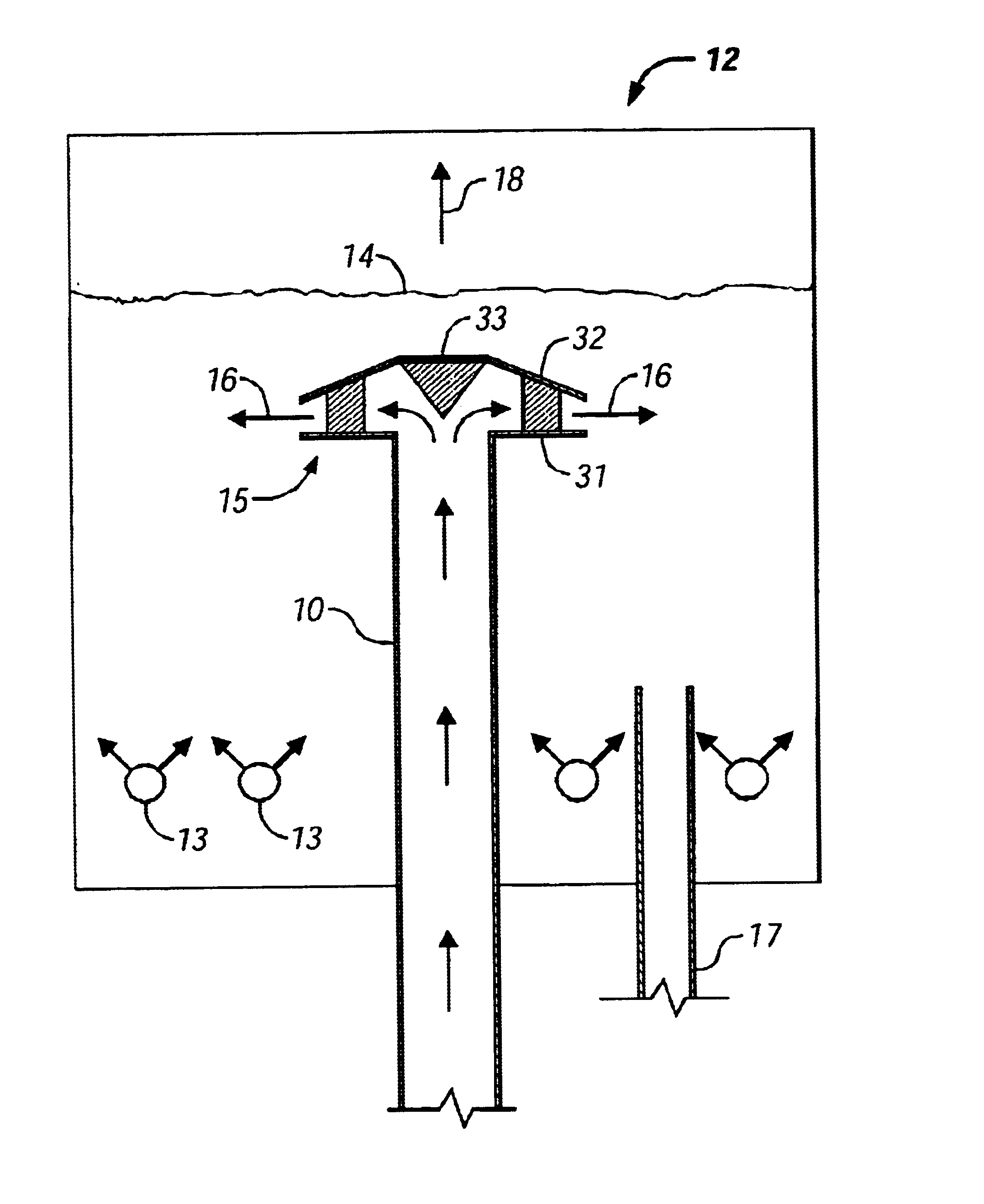
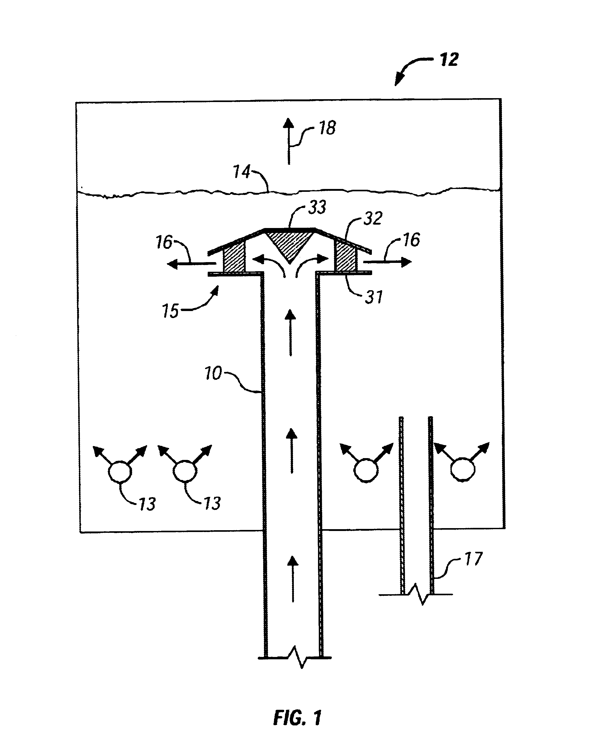
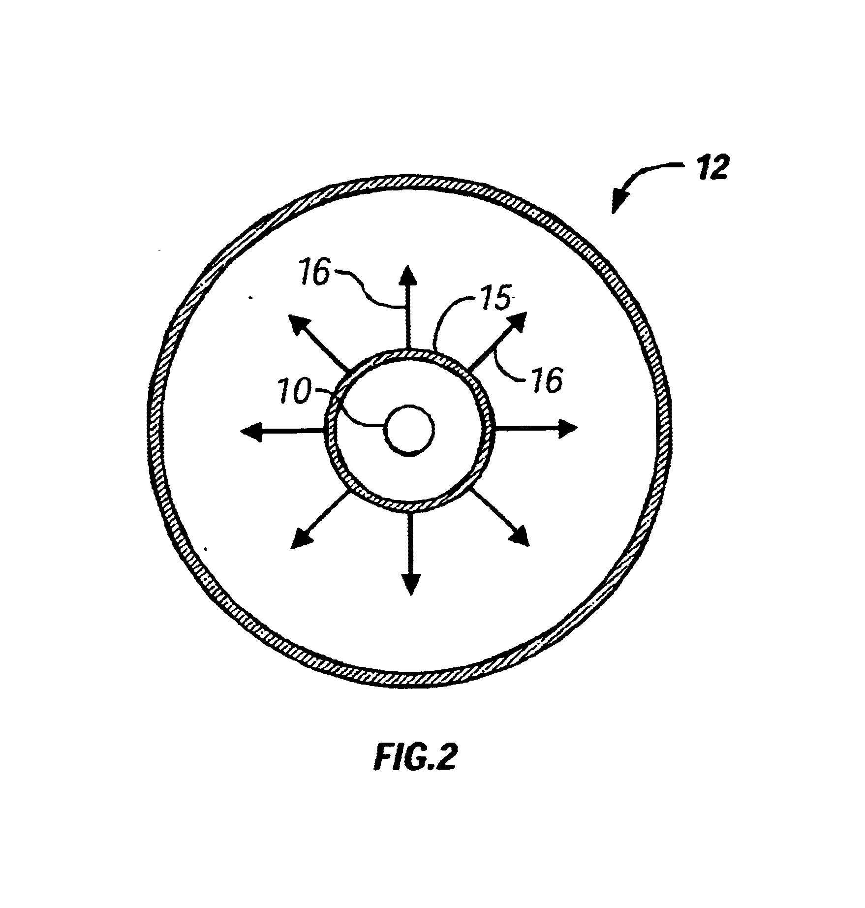
In the following illustrative embodiment, performance tests were conducted on a regenerator before and after the installation of one embodiment of the spent catalyst distributor of the present invention according to FIGS. 3A and 3B. FIG. 4 shows the prior art spent catalyst distributor that was replaced with an embodiment of the present invention. Table 1 below shows a comparison of some performance parameters before and after the installation.

Benefits of improved distribution of spent catalyst and transport gas in the regenerator can be utilized advantageously in numerous ways. In the above illustrative embodiment, the operator was able to run the regenerator with substantially less supplemental oxygen and reduce the carbon on the regenerated catalyst, while maintaining the required coke burning capacity. Both of these advantages bring substanti...


PUM

PropertyMeasurementUnit
Angleaaaaaaaaaa
Angleaaaaaaaaaa
Angleaaaaaaaaaa

Abstract

The present invention is related to methods and apparatus for improving distributions of both spent catalyst and transport gas into a regenerator of a fluid catalytic cracking unit. Spent catalyst and transport gases move upwardly through a spent catalyst riser and are diverted in a radially outward direction by a deflector cone. The catalyst and transport gas are re-mixed as they move radially outward between two disks before discharging from the outer edges (perimeter) of the distributor into the regenerator in a substantially uniform radial direction. The distributor is adapted to provide continuous discharge from its perimeter so as to cover the entire cross-section of the regenerator.

Description

1. Field of the InventionThe present invention is related to methods and apparatus for improving distributions of both spent catalyst and transport gas into a regenerator of a fluid catalytic cracking unit.2. Description of Related ArtIn a typical Fluid Catalytic Cracking Unit (FCCU) consisting of a regenerator, a riser reactor and a stripper, such as that shown in U.S. Pat. No. 5,562,818 to Hedrick which is incorporated herein by reference, finely divided regenerated catalyst is drawn from the regenerator through the regenerator standpipe and contacts with a hydrocarbon feedstock in a lower portion of a reactor riser. Hydrocarbon feedstock and steam enter the riser through feed nozzles. The mixture of feed, steam and regenerated catalyst, which has a temperature of from about 200.degree. C. to about 700.degree. C., passes up through the riser reactor, converting the feed into lighter products while a coke layer deposits on the surface of the catalyst, temporarily deactivating the c...

Claims


Application Information

Patent Timeline
IPC IPC(8): C10G11/18C10G11/00B01J8/24
CPCC10G11/182B01J8/18B01J8/0025B01J2208/00752
Inventor CHEN, YE-MONPATEL, MAHENDRA SONABHAI
Owner SHELL OIL CO
Why Eureka
Try Eureka