Engine control system

a control system and engine technology, applied in the direction of electric controllers, electric control, instruments, etc., can solve the problems of inability to obtain sufficient drive force, dangerous state of difficulty in stopping the vehicle, and inability to carry out hill climbing evacuation operations

Inactive Publication Date: 2004-09-28
MITSUBISHI ELECTRIC CORP
View PDF26 Cites 28 Cited by
  • Summary
  • Abstract
  • Description
  • Claims
  • Application Information

AI Technical Summary

Benefits of technology

The operation control system shown FIG. 17b is applied to the above-described Example 1, in which under the abnormal state that the throttle valve opening at the time of stopping the motor is not less than the default opening. In this operation system, the supply fuel control means 4 is controlled in such a manner that the engine speed may be not more than the threshold value set by the upper limit engine speed setting means 2c.

Problems solved by technology

However, in the case that the above-described safe throttle valve opening is small, a problem exists in that even if the brake is released, any sufficient drive force cannot be obtained, and therefore any hill climbing evacuation operation cannot be carried out.
On the contrary, in the case that the safe throttle valve opening is excessively large, there arises a dangerous state of having difficulty in stopping the vehicle in spite of sufficiently depressing the brake pedal.
Further, it is necessary to take into consideration such a problem that a default return is not carried out properly due to a mechanical trouble in the throttle valve opening control.
However, in this prior art, the throttle valve opening is so small that a sufficient vehicle speed cannot be obtained.
However, a most serious problem exists in this type of control system that the accelerator pedal cannot perform a function of proportionally increasing or decreasing the vehicle speed or engine speed.
Accordingly, a problem exists in this type of control system that even if the upper limit engine speed is regulated so as to be not more than the threshold value, the actual throttle valve opening is indefinite, and that engine drive torque is varied depending upon the valve opening.
Further there is a possibility that braking by means of the brake pedal becomes difficult in the case of large valve opening.
Therefore, supposing that the upper limit threshold engine speed might be lowered, any sufficient drive force cannot be obtained.
In particular, a problem exists in that the hill climbing evacuation travelling cannot be carried out at all in the case of small valve opening.
However, a problem exits in that drive torque of the engine becomes decreased due to the target valve opening being suppressed, whereby any sufficient hill climbing performance cannot be obtained.
In particular, a problem exits in that any technique of identifying non-defective, wherein if one of the abnormality determination means such as APS or TPS is in failure, the other one is automatically selected, is not employed.
A further problem exits in that the suppression of the target valve opening is not carried out in a rational and quantitative manner.
Particularly, supposing that the output voltage detected by the accelerator position sensor might be excessively large when the accelerator pedal is returned to its position, there may arise a dangerous state difficult to stop by means of the brake pedal.

Method used


Image

  • Engine control system
  • Engine control system
  • Engine control system

Examples


embodiment 1

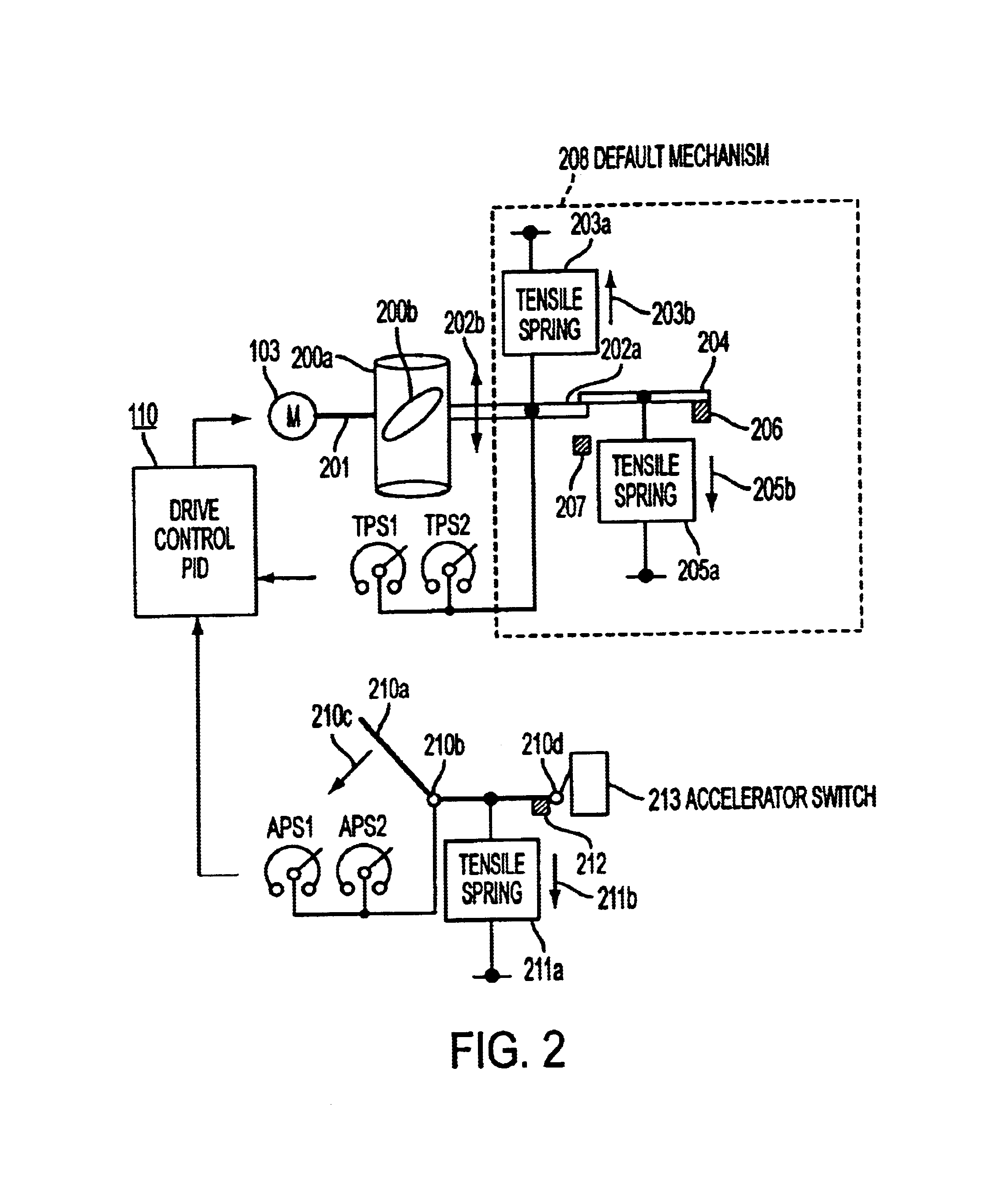
FIG. 2 showing a schematic diagram to explain a mechanism in which essential part is the actuator of the invention is hereinafter described.

In FIG. 2, numeral 200a designates an intake throttle including a throttle valve 200b. Numeral 201 designates a rotary shaft of the motor 103 that controls the open / close of the throttle valve 200b. Numeral 202a designates a direct coupled oscillating part interlocking with the rotary shaft 201, and in the drawing this rocking part 202a is illustrated so as to vertically move in the direction of an arrow 202b for reasons of better understanding.

Numeral 203a designates a tensile spring that gives an impetus to the above-described direct coupled oscillating part 202a in the direction of an arrow 203b (valve-opening direction). Numeral 204 designates a return member that is given an impetus in the direction of an arrow 205b (a valve-closing direction) by means of a tensile spring 205a, and overcomes the above-described tensile spring 203a to retur...

embodiment 2

Consequently, it is desired that the operation according to this evacuation operation mode is possible only by the main CPU111 even if the sub CPU121 is abnormal. Details thereof will be described later referring to FIG. 15.

FIG. 15 is a flowchart to explain an operation at third and fourth non-defective selection means according to Embodiment 2 of the invention. This operation is carried out in the case that the operation mode 1-2 is controlled only by the main CPU111, or the APS and TPS are relatively abnormal although the APS or TPS is not individually abnormal, and it cannot be identified which one is abnormal.

In FIG. 15, numeral 910 is an operation start step of the main CPU that is regularly activated by the interrupt operation. Numeral 911 is a step that acts subsequently to the start step 910 and measures an inflow air amount using the signal of an air flow sensor mounted on an intake tube not shown. Numeral 912 is a step that acts subsequently to the measurement step 911 and...


PUM


Abstract

Evacuation operation performance is improved when any abnormality occurs in an electronic throttle control system.When any serious abnormality occurs, a first abnormality storage element (133) operates, a load relay for a power supply circuit (104a) of a throttle valve open / close controlling motor (103) is de-energized to operate a first alarm and display (109a). Thus a first device carries out the evacuation operation by a fuel cut control.When any slight abnormality occurs, a second abnormality storing element (136) comes to actuate thereby a second alarm and display (109b) being operated. Thus a second device carries out the evacuation operation using together a throttle valve opening control by the motor 103 and the fuel cut control.

Description

1. Field of the InventionThe present invention relates to an electronic control system of an intake amount for an engine that is used in an engine control unit (ECU) for carrying out an ignition control, a fuel injection control and the like of an automobile engine, particularly in a composite type ECU in which an electronic throttle control function for controlling a throttle valve opening by means of an electric motor is added, and in which safety of the additional function and evacuation operation performances under abnormal state are improved.2. Background ArtAn electronic throttle control system for controlling a throttle valve opening for an intake of an engine in accordance with a depression degree of an accelerator pedal using an electric motor has been widely put into practical use. Recently a wireless type that does not have any accelerator wire has been coming into wide use.This type of electronic throttle control system is arranged such that when a power supply for the e...

Claims


Application Information

Patent Timeline
Patent Type & Authority Patents(United States)
IPC IPC(8): F02D31/00F02D41/22F02D11/10G05B23/02G05B9/02F02D29/02F02D9/02F02D41/08F02D41/32F02D45/00
CPCF02D11/107F02D31/009F02D41/22Y10T477/347F02D2200/0404F02D2200/602F02D2041/227
Inventor HASHIMOTO, KOHJINAKAMOTO, KATSUYA
Owner MITSUBISHI ELECTRIC CORP
Why Eureka
Try Eureka