
Installation for very long term storage of heat-generating products such as nuclear waste

a technology for installation and storage of nuclear waste, which is applied in the direction of stationary tubular conduit assemblies, reactor fuel elements, protective foundations, etc., can solve the problems of hazardous calorific products such as nuclear waste storage, dangerous for the environment, and the cooling is achieved through a primary circui

Inactive Publication Date: 2004-10-12
COMMISSARIAT A LENERGIE ATOMIQUE ET AUX ENERGIES ALTERNATIVES
View PDF19 Cites 35 Cited by
  • Summary
  • Abstract
  • Description
  • Claims
  • Application Information

AI Technical Summary

Benefits of technology

The use of means forming a thermosiphon integrated into a jacket closely surrounding the container makes it possible to provide efficient evacuation of the heat released by the products contained in the container, without however risking any dispersion of contamination in the event of an accident. Also, the jacket forms a heat shield between the container and the wall of the cavity. The latter, generally made in concrete if the stored products are nuclear waste, is therefore cooled efficiently and in homogeneous manner in the same way as the actual container. Accelerated ageing of the concrete, container welds and container contents is therefore avoided. In addition, it is possible to have knowledge of and efficiently adjust the surface temperature of the container and the temperature of the wall of the well or trench. This also makes it possible to pilot the conditions of storage in accordance with usual hypotheses (not generally heeded in existing installations) according to which the temperature of the concrete surface is known and fixed. Such installation also has the advantage of allowing the cold source, positioned above the cavity, to be adapted to changes over time in the heat released by the stored products.
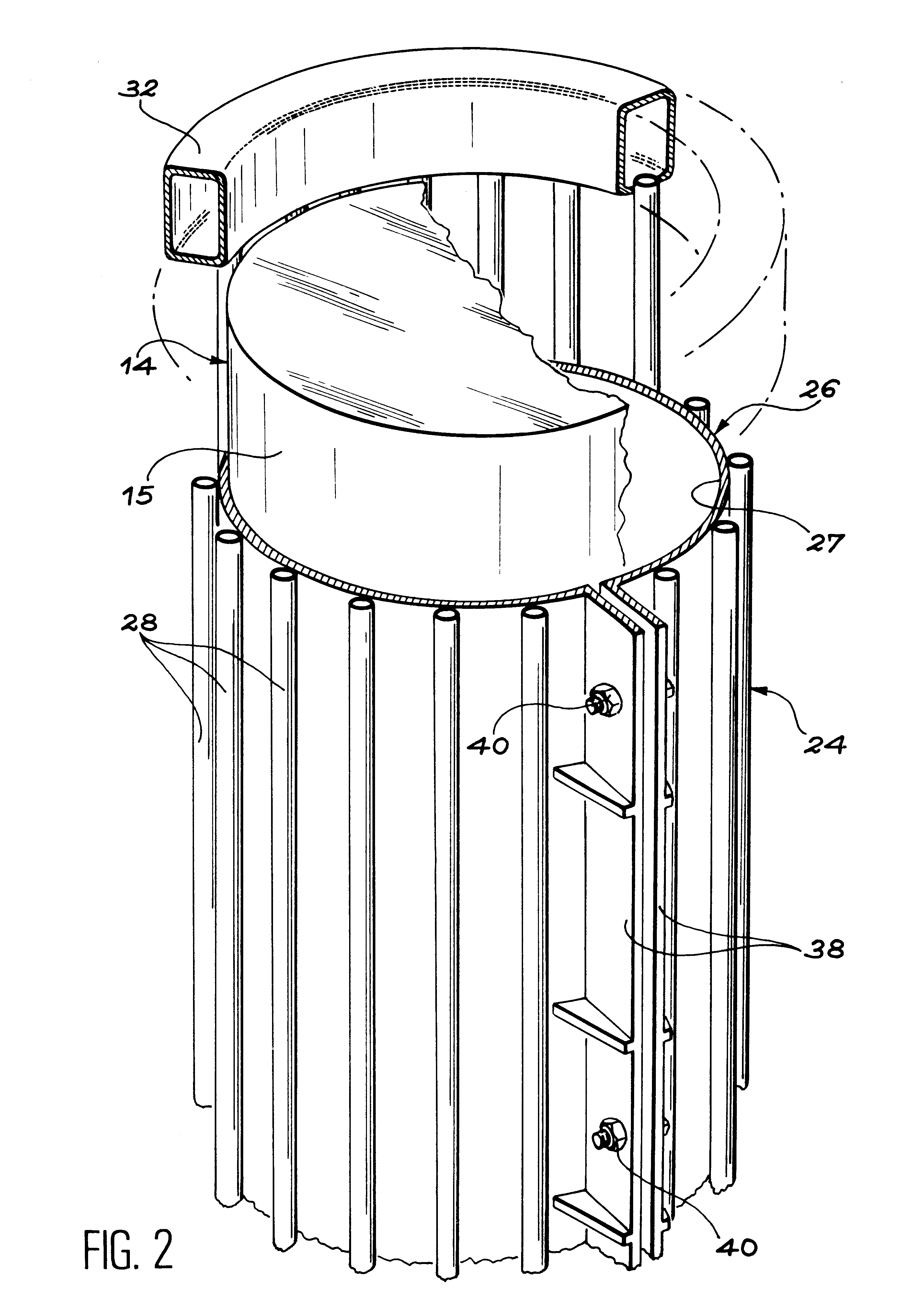
In this case, the jacket is advantageously open and made in a flexible, elastic material such as metal so that it can occupy a natural state in which it is spaced away from the container. In this natural state the jacket can be easily mounted and dismounted. In this case, releasable clamp means are provided, to apply the jacket tightly around the container at the time of placing in storage.

Problems solved by technology

The storage of hazardous calorific products such as nuclear waste is a major problem for which a certain number of solutions have already been put forward.
One notable disadvantage of said type of installation is that cooling is achieved via a primary circuit, in direct contact with the container walls.
This type of arrangement is dispersive in the event of an incident and therefore dangerous for the environment.
In addition, it only allows very limited evacuation of the heat flow.
Firstly, since cooling is achieved only inside the concrete walls themselves, the surfaces of these walls delimiting the cavities are heated directly by the stored products. The consequence is weakening of the concrete at least on the surface. Also, the temperature of the containers remains very high, leading to rapid ageing of their welds. Finally, with such storage installations it is not possible to control the outside temperature and therefore the inside temperature of the containers and this may, for example, lead to destruction of the cladding of the irradiated fuel.
In this case, almost the same disadvantages are found as with the previous known technique.
Also, since the cooling circuit passes locally through the surfaces of the concrete walls delimiting the cavities, these surfaces are subjected to non-homogeneous heat stresses which lead to accelerated ageing of the concrete.
This known solution is characterized by corrosion problems due to the fact that the containers are immersed in water.
Also, any leak from the cooling circuit entails a contamination risk if the stored products are nuclear waste.
Further, the maintenance of this type of storage device is particularly heavy.
The efficacy of said device is relatively limited and does not prevent major heating of the containers and well walls.
Also, a substantial heat gradient exists between the containers placed at the bottom of the well and the containers nearer to the surface.
Consequently, surface weakening of the concrete and accelerated ageing of the container welds and dissipater tube (which is not interchangeable) are practically unavoidable.

Method used


Image

  • Installation for very long term storage of heat-generating products such as nuclear waste
  • Installation for very long term storage of heat-generating products such as nuclear waste
  • Installation for very long term storage of heat-generating products such as nuclear waste

Examples


Embodiment Construction

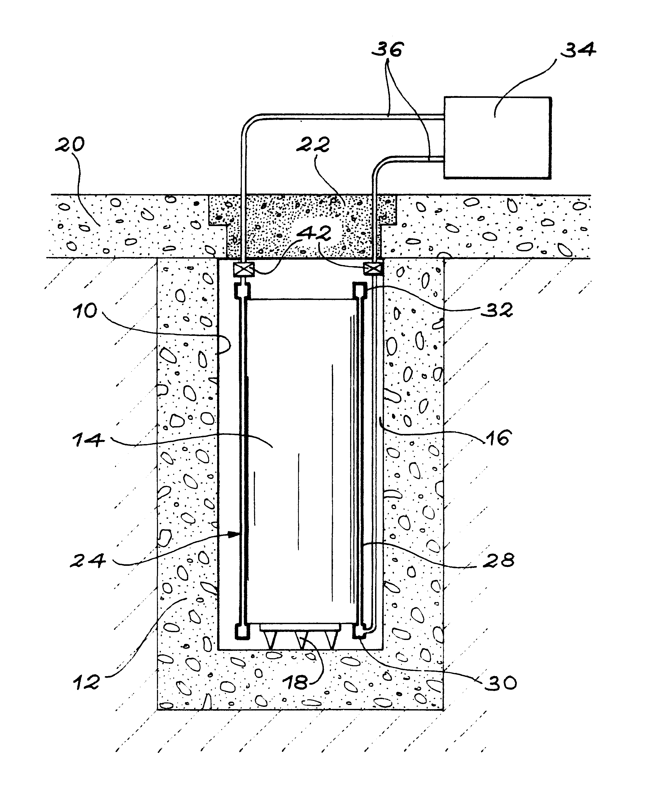
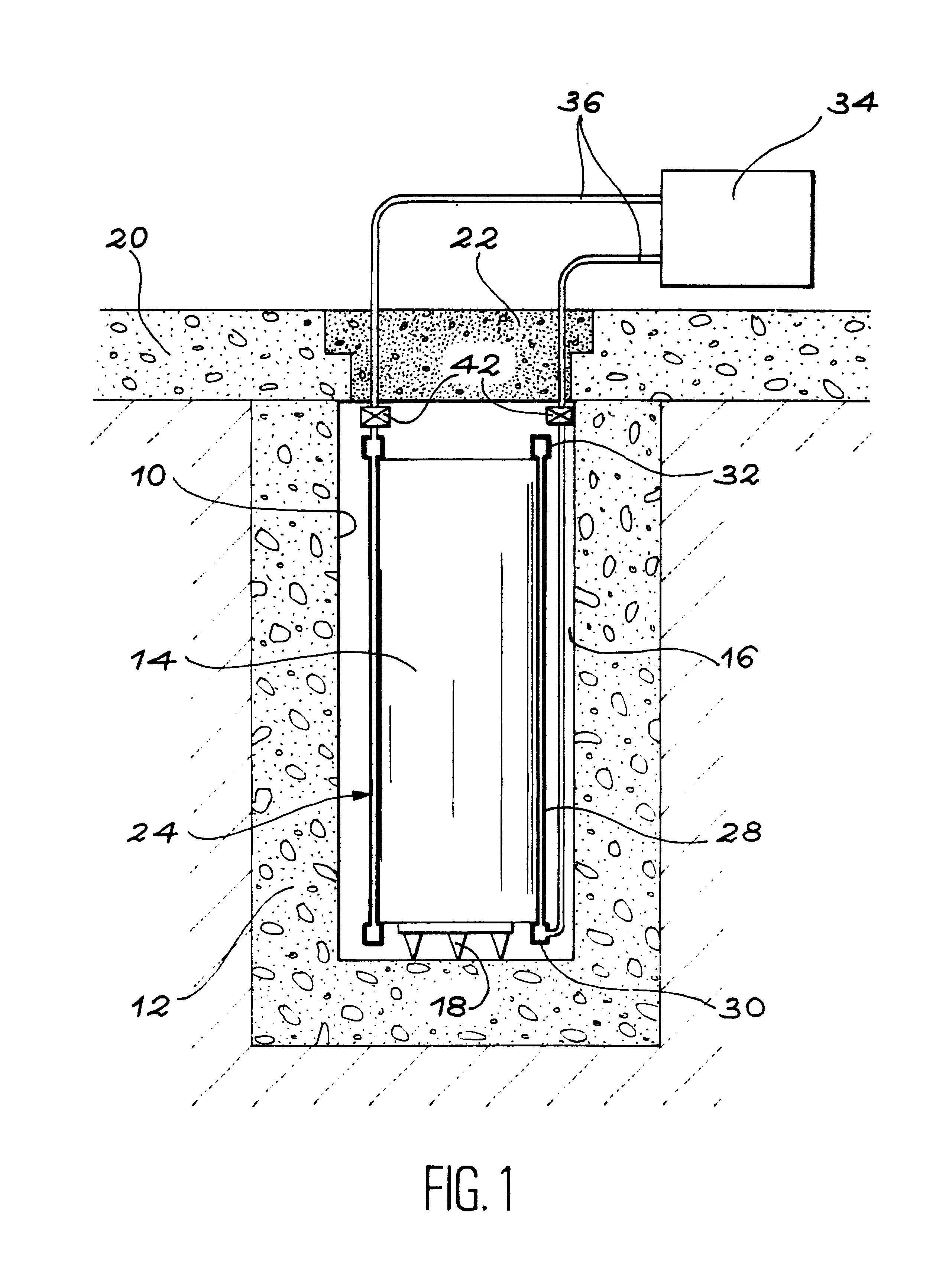
FIG. 1 is a very schematic diagram of part of a very long-term storage installation for calorific products, such as nuclear waste, built in accordance with the invention.

The installation comprises at least one sealed cavity 10, such as an embedded trench, whose sides and bottom are delimited by concrete walls 12.

In the described embodiment, cavity 10 is in the form of a rectilinear embedded trench. This trench is able to house several containers 14 in which the products to be stored are packaged. However, the shape of cavity 10 may be different while remaining within the scope of the invention. Therefore, it is possible for each of containers 14 to be placed in a separate, individual cavity.

In similar manner, the containers 14 used to confine the products to be stored are metal containers whose size and shape may vary while remaining within the scope of the invention. In the embodiment illustrated by way of example, the containers 14 are of cylindrical shape and are placed side by s...


PUM


Abstract

A very long term storage installation for calorific products such as nuclear waste, comprises at least one closed cavity (10), in which at least one product confinement container is housed (14). To evacuate the heat released by the stored products, each container (14) is surrounded by a jacket (26) associated with a thermosiphon (24) whose cold source is formed of an air condenser provided above a slab (20) sealing the top part of the cavity. The jacket (26) is preferably interchangeable and tightly surrounds the container (14).

Description

The invention concerns an installation intended to ensure the storage over the very long term of calorific products likely to release large quantities of heat which may decrease in time.The term "storage" designates the reversible storage of packaged products, accompanied by evacuation of the heat released by these products. By the adjective "reversible" is meant that the stored products may be taken out from storage.The expression "very long-term" means at least fifty years and, preferably, several periods of fifty years.One privileged application of the installation of the invention concerns the storage of nuclear waste having very high long-term activity, such as irradiated fuel in nuclear reactors.PRIOR ARTThe storage of hazardous calorific products such as nuclear waste is a major problem for which a certain number of solutions have already been put forward.Among such solutions, reference will only be made to those which ensure passive cooling of the products without the supply...

Claims


Application Information

Patent Timeline
IPC IPC(8): G21F5/00G21F5/10G21C19/06G21F9/34G21F9/36
CPCG21F5/10F28D15/0266F28D7/0041F28D15/00G21Y2002/201G21Y2002/206G21Y2002/402G21Y2004/30Y10S588/90G21Y2002/60G21F5/005
Inventor BADIE, MICHELIRACANE, DANIELLE DUIGOU, ALAINPEULVE, JACQUES
Owner COMMISSARIAT A LENERGIE ATOMIQUE ET AUX ENERGIES ALTERNATIVES
Learn More