Automatic transmission of motor vehicle
a technology of automatic transmission and motor vehicle, which is applied in the direction of mechanical equipment, transportation and packaging, etc., can solve the problems of increasing the axial length of the transmission, increasing the difficulty of installing the transmission, and increasing the weight and cost of the transmission
- Summary
- Abstract
- Description
- Claims
- Application Information
AI Technical Summary
Benefits of technology
Problems solved by technology
Method used
Image
Examples
first embodiment
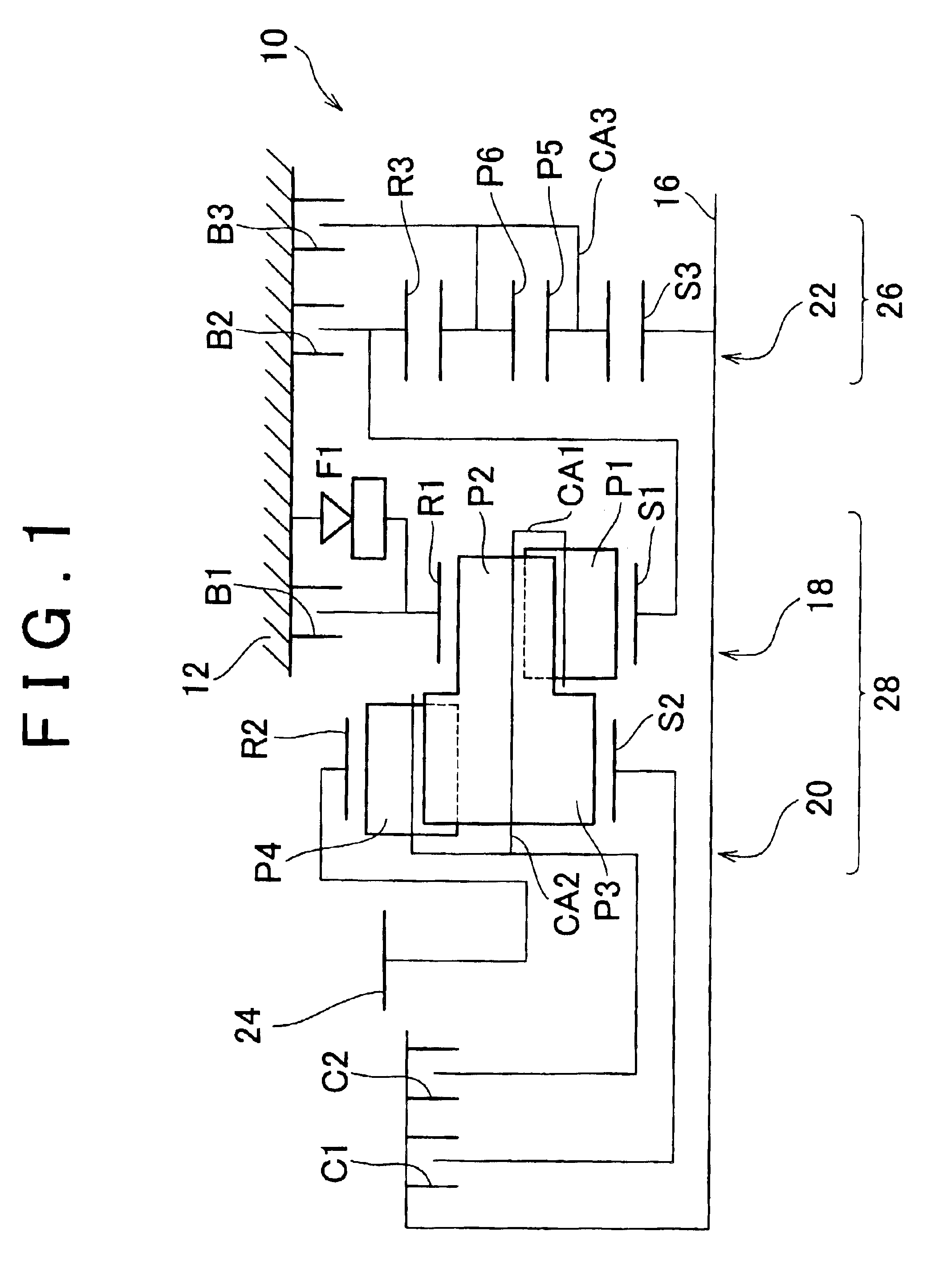
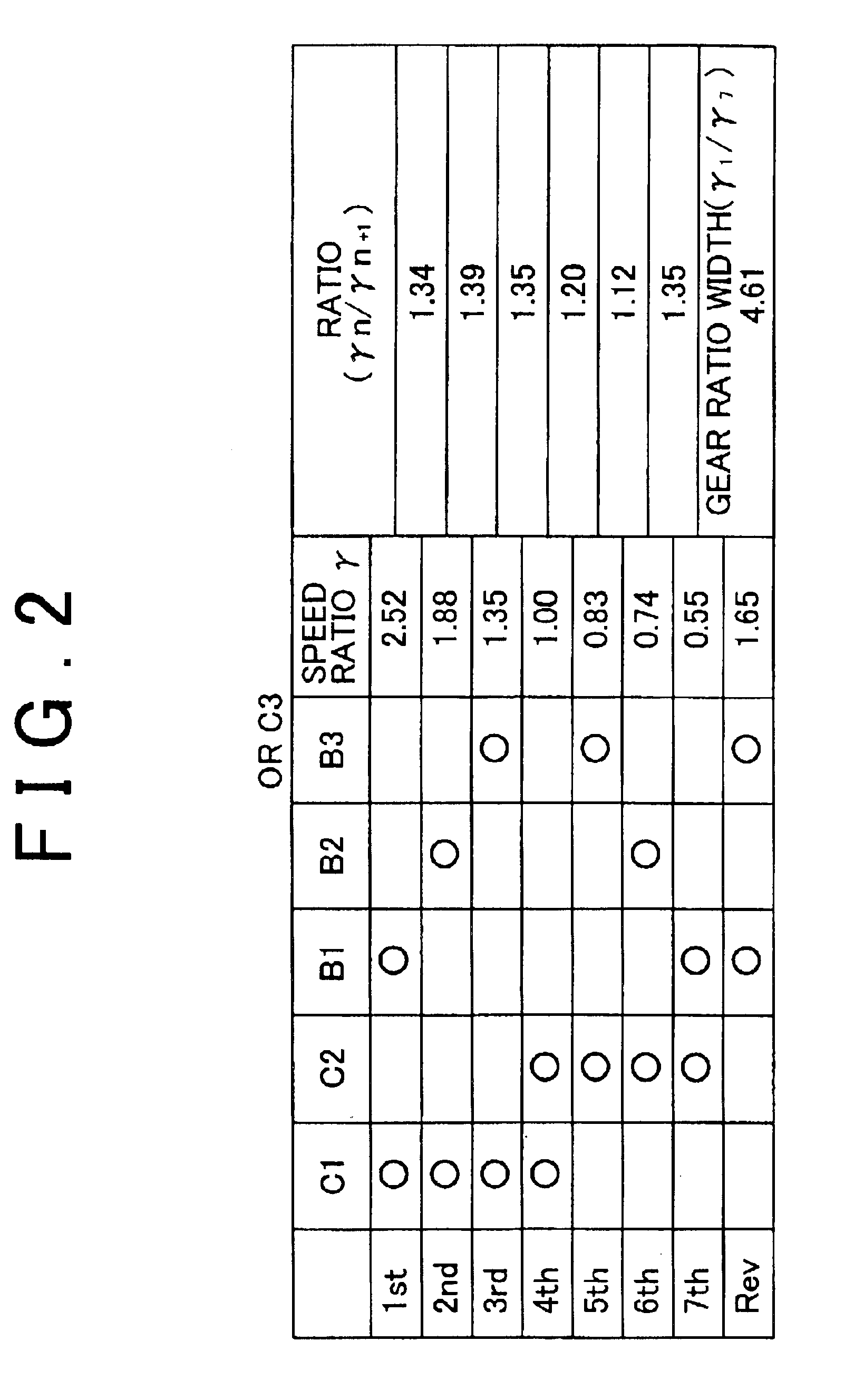
FIG. 1 schematically shows a planetary gear type automatic transmission (hereinafter simply referred to as "transmission") 10 of a motor vehicle according to the invention. FIG. 2 is an operation table indicating engaging elements and the gear ratio (or speed ratio) with respect to each of a plurality of gear stages or speeds to be established by the transmission. FIG. 3 is a nomogram plotted with respect to the transmission of FIG. 1.
Referring first to FIG. 1, the transmission 10 receives rotary power transmitted from an engine (not shown) to an input shaft 16 thereof, changes the speed of rotation at a given gear ratio, and transmits the power from an output gear 24 to right and left driving wheels, via a propeller shaft (not shown), a differential gear unit (not shown), and other members. The transmission 10 includes a torque converter (not shown) provided with a lockup clutch, the input shaft 16 coupled to the torque converter, a third planetary gear set 22, a first planetary ge...
third embodiment
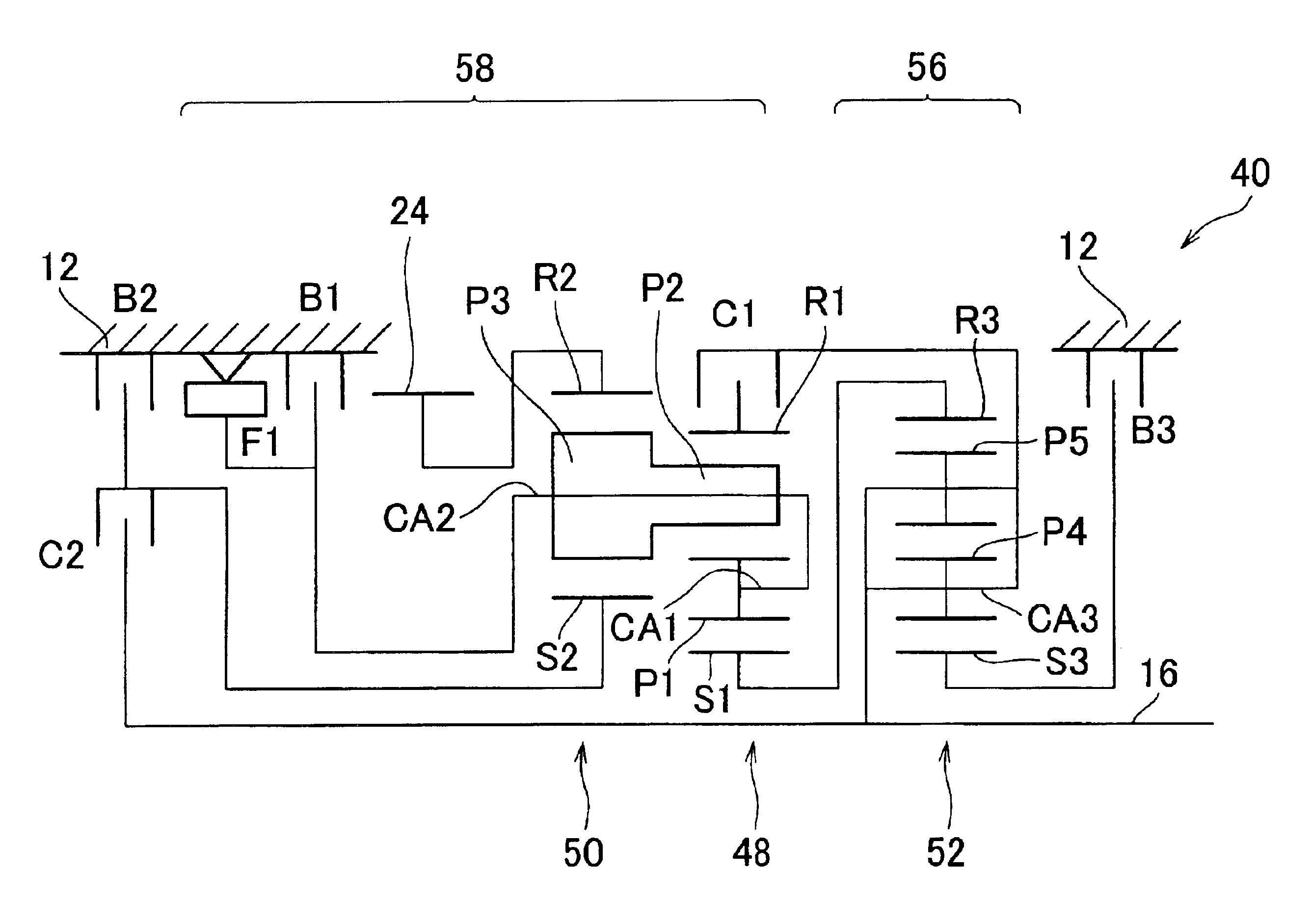
In the third embodiment as described above, the second pinion P2 of the double-pinion type first planetary gear set 48 and the third pinion P3 of the single-pinion type second planetary gear set 50 are coupled to each other on the same axis so that these pinions P2, P3 are rotated as a unit. Like Ravigneaux type planetary gear trains, this arrangement requires a further reduced number of components and further reduced axial length, which result in further reduction in the size and cost of the transmission 40.
In the third embodiment as described above, the main power transmitting portion 58 includes the first planetary gear set 48 and the second planetary gear set 50, and the first rotating element RE1 is the second sun gear S2, the second rotating element RE2 consists of the first carrier CA1 and the second carrier CA2, the third rotating element RE3 is the first ring gear R1, the fourth rotating element RE4 is the second ring gear R2, and the fifth rotating element RE5 is the first...
fifth embodiment
In the main power transmitting portion 68 of the transmission 70 of the fifth embodiment, parts of the first sun gear S1, first carrier CA1 and the first ring gear R1 of the first planetary gear set 76 and the second sun gear S2, second carrier CA2 and the second ring gear R2 of the second planetary gear set 78 are coupled to each other so as to provide five rotating elements RE1 through RE5, as shown in the monogram of FIG. 10. In the monogram of FIG. 10, the speeds of rotation of the five rotating elements RE1 through RE5 are represented by straight lines, and the first rotating element RE1, second rotating element RE2, third rotating element RE3, fourth rotating element RE4 and the fifth rotating element RE5 are arranged in this order from one end (i.e., the left end in FIG. 10) to the other end (i.e., the right end in FIG. 10). In the transmission 70 of this embodiment, the first rotating element RE1 (S1) is selectively inhibited from rotating by the second brake B2, and is sele...
PUM
 Abstract
Description
Claims
Application Information
 - R&D
- Intellectual Property
- Life Sciences
- Materials
- Tech Scout
- Unparalleled Data Quality
- Higher Quality Content
- 60% Fewer Hallucinations
Browse by: Latest US Patents, China's latest patents, Technical Efficacy Thesaurus, Application Domain, Technology Topic, Popular Technical Reports.
© 2025 PatSnap. All rights reserved.Legal|Privacy policy|Modern Slavery Act Transparency Statement|Sitemap|About US| Contact US: help@patsnap.com


