Leak-check apparatus of fuel-vapor-processing system, fuel-temperature estimation apparatus and fuel-temperature-sensor diagnosis apparatus

a technology of fuel-vapor processing system and leak detection apparatus, which is applied in the direction of fluid-tightness measurement, instruments, machines/engines, etc., can solve the problems of low accuracy, exhausting the battery, and difficulty in high-degree leak detection precision

Inactive Publication Date: 2004-10-26
DENSO CORP
View PDF4 Cites 45 Cited by
  • Summary
  • Abstract
  • Description
  • Claims
  • Application Information

AI Technical Summary

Benefits of technology

It is another object of the present invention to provide a leak-check apparatus capable of detecting a leak in a fuel-vapor-processing system with a high degree of precision and reducing the amount of consumed power generated by the battery in a stopped state of the engine.
According to a seventh aspect of the present invention, a fuel-temperature sensor is diagnosed for existence / non-existence of an abnormality on the basis of a relation between an estimated value of the fuel temperature and a temperature value detected by the fuel-temperature sensor. If the difference between an estimated value of the fuel temperature and a temperature value detected by the fuel-temperature sensor is beyond a range of the normal state, for example, the result of the diagnosis of the fuel-temperature can be set to indicate that the sensor is abnormal. As an alternative, the fuel-temperature sensor is diagnosed for existence / non-existence of an abnormality on the basis of a relation between a change in fuel-temperature estimated value and a change in fuel-temperature-sensor detected value. This is because the estimated value of the fuel temperature varies in dependence on how an initial value of the estimated fuel temperature is set. By using the change in fuel-temperature estimated value in place of the estimated value of the fuel temperature, this problem can be solved. This is because the change in fuel-temperature estimated value is all but independent of how an initial value of the estimated fuel temperature is set. Thus, by diagnosing the fuel-temperature sensor for existence / non-existence of an abnormality on the basis of a relation between a change in fuel-temperature estimated value and a change in fuel-temperature-sensor detected value, the fuel-temperature sensor can be diagnosed for existence / non-existence of an abnormality with a high degree of precision even if the initial value of the estimated fuel temperature changes more or less.

Problems solved by technology

It is thus difficult to check a leak with a high degree of precision during a running state of the engine.
However, leak-check processing, which is carried out after the engine is stopped, exhausts the battery.
When the ambient temperature is low, however, the temperature of fuel in the fuel tank may not increase.
Thus, when the passage of the system is opened after the leak-check processing, a flow is generated in the system due to a difference in pressure between the system and the atmosphere.
If a flow is generated in a canister, for example, fuel vapor transits to an undesirable state in some cases.
In the case of a small leak, however, it takes a long time to generate a detectable change in pressure.
Thus, in order to detect a small leak, a long check time is required.
During such a long check time, however, it is quite within the bounds of possibility that the operating condition of the engine changes.
It is thus difficult to detect a small leak.
However, the fuel-temperature sensor increases the number of components and brings about an increase in assembly man-hour.
As a result, it is difficult to distinguish a leaked state and the normal state from each other.

Method used


Image

  • Leak-check apparatus of fuel-vapor-processing system, fuel-temperature estimation apparatus and fuel-temperature-sensor diagnosis apparatus
  • Leak-check apparatus of fuel-vapor-processing system, fuel-temperature estimation apparatus and fuel-temperature-sensor diagnosis apparatus
  • Leak-check apparatus of fuel-vapor-processing system, fuel-temperature estimation apparatus and fuel-temperature-sensor diagnosis apparatus

Examples


first embodiment

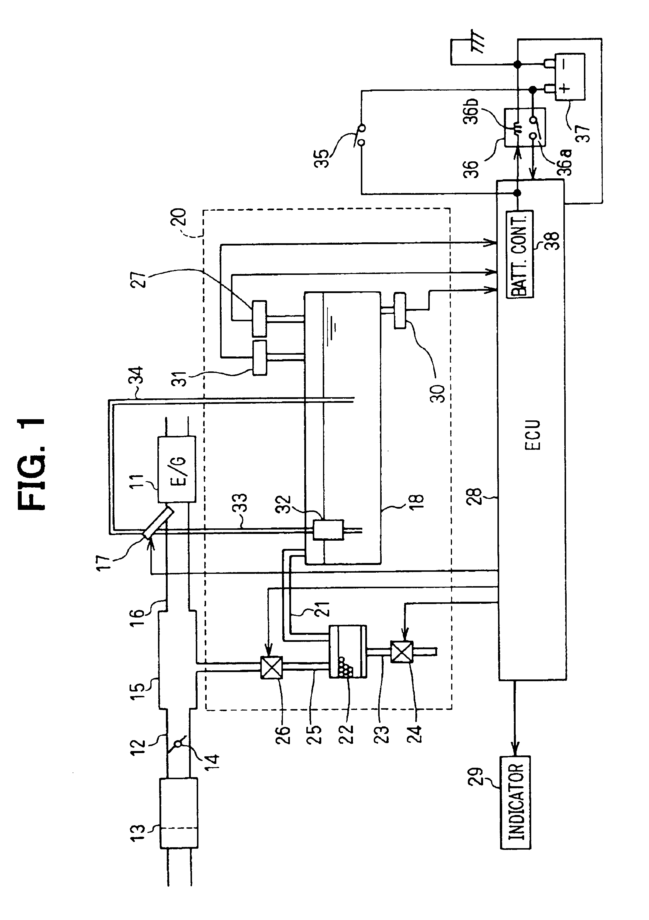
The following description explains an overall configuration of a fuel-vapor-processing system, which is implemented by a first embodiment of the present invention, by referring to FIG. 1 showing the configuration in a plain and simple manner. An air cleaner 13 is provided on the upstream side of an intake pipe 12 of the engine 11. Air passing through the air cleaner 13 flows into each cylinder of the engine 11 by way of a throttle valve 14, a surge tank 15 and an intake manifold 16. On the intake manifold 16 of each cylinder, a fuel injection valve 17 is provided. Fuel is supplied to each fuel injection valve 17 by a fuel pump 32 provided in a fuel tank 18 by way of a fuel pipe 33. A pressure regulator is provided on a delivery pipe not shown in the figure. Excess fuel is returned to the fuel tank 18 by way of a return pipe 34.

Next, the configuration of the fuel-vapor-processing system 20 is explained. The fuel tank 18 is connected to a canister 22 by a gas passage 21. The canister ...

second embodiment

In this embodiment, in order to reduce the consumption of power generated by the battery 37 in a stopped state of the engine, the frequency at which the leak-check program is executed in the stopped state of the engine is decreased.

FIG. 9 is a diagram showing the configuration of a system, which is implemented by this embodiment, in a simple and plain manner. The embodiment includes an additional leak-check-undone timer 40 for verifying the state of execution of the engine-stopped-state leak-check program. Unlike other components consuming power generated by the battery 37, the leak-check-undone timer 40 is driven by a small mount of power not generated by the battery 37. An example of the other components is the ECU 28. A flowchart shown in FIG. 10 represents count processing of the leak-check-undone timer 40. The count processing represented by this flowchart is carried out typically once 1 minute. At a step S300, a previous timer value ENDTimer is incremented by 1 and used as the...

third embodiment

In the first and second embodiments, the tank-internal-pressure monitor program is executed in order to restore the normal state. For this reason, it is feared that the ECU 28 inevitably consumes power generated by the battery 37.

In order to solve this problem, in this embodiment, only the negative-pressure monitor program executed in the running state of the engine determines the state of the normal-state restoration for the purpose of reducing the amount of power consumed in a stopped state of the engine 11.

FIG. 14 is a flowchart representing the tank-internal-pressure monitor program provided by this embodiment. At a step S400, the indicator 29 is examined to determine whether the indicator 29 has been turned on due to a leak through a hole with a diameter of about 0.5 or 1.0 mm. If the indicator 29 has been turned on, by consideration of the power consumption by the ECU 28, the execution of this routine is ended without executing the tank-internal-pressure monitor program. If th...


PUM


Abstract

A fuel-vapor-processing system for an engine has a canister for accumulating fuel evaporation gas. The system has a leak-check apparatus for checking a leak on passages. The leak-check apparatus includes a leak-check means for carrying out leak-check processing when the engine if in a stopped state. The leak-check means operates only if a predetermined condition is satisfied. It is thus possible to reduce the number of times the leak-check processing is carried out and, hence, possible to reduce power consumption. For example, only if a relatively small leak is detected when the engine is in a running state, the leak-check processing is carried out in a stopped state to verify existence of such a leak. In the leak-check processing, the temperature of fuel, detected by a sensor or an estimated value, may be taken into consideration.

Description

This application is based on Japanese Patent Applications No. 2001-223764 filed on Jul. 25, 2001, No. 2001-226914 filed on Jul. 27, 2001, No. 2001-241509 filed on Aug. 9, 2001, No. 2001-249345 filed on Aug. 20, 2001, and No. 2001-266638 filed on Sep. 4, 2001 the contents of which are incorporated herein by reference.1. Field of the InventionThe present invention relates to a leak-check apparatus of a fuel-vapor-processing system, a fuel-temperature estimation apparatus and a fuel-temperature-sensor diagnosis apparatus.2. Description of Related ArtU.S. Pat. No. 6,082,337 (JP-A-11-101162) discloses an apparatus, which is used for checking a leak on a passage of a fuel-vapor-processing system during a running state of the engine. In a running state of the engine, however, the level of fuel in a fuel tank varies. It is thus difficult to check a leak with a high degree of precision during a running state of the engine.On the other hand, JP-A-6-81727 (Japan Patent No. 2,745,991) discloses...

Claims


Application Information

Patent Timeline
Patent Type & Authority Patents(United States)
IPC IPC(8): F02M25/08G01M99/00
CPCF02M25/0809
Inventor WAKAHARA, KEIJIMORINAGA, SYUJIROMAEGAWA, YOSHINORIMIWA, MAKOTO
Owner DENSO CORP
Why Eureka
Try Eureka