Method for operating a combined-cycle power station

a combined-cycle power station and power generation technology, applied in steam engine plants, machines/engines, mechanical equipment, etc., can solve the problems of gas turbo group using up a large number of equivalent operating hours, increasing the power output above the rated power output, and affecting the life of components in the hot gas path

Inactive Publication Date: 2004-11-02
ANSALDO ENERGIA IP UK LTD
View PDF9 Cites 20 Cited by
  • Summary
  • Abstract
  • Description
  • Claims
  • Application Information

AI Technical Summary

Problems solved by technology

Increasing the power output above the rated power output is in this case subject to particularly stringent requirements.
However, nowadays, modern gas turbo groups are designed for efficiency reasons such that they operate in a wide upper power output range in the region of the maximum permissible design temperatures for continuous operation at the rated power output (upper process temperature), that is to say they are at their design temperature limit for continuous operation.
Increases in the power output in this range thus lead to the design temperatures being exceeded when the operating regime for normal operation is departed from, and this has a negative effect on the life, in particular of the components affected in the hot gas path.
This has the disadvantage that this method of operation as a departure from the normal regime results in the gas turbo group using up a very large number of equivalent operating hours (EOH=equivalent operating hours, OH=operating hours) and losing a very large number of operating life hours (for example 1.3 EOH / OH for steam injection or 1.5 EOH / OH for frequency response).
This is particularly true when the overload has to be maintained for a long time.

Method used


Image

  • Method for operating a combined-cycle power station
  • Method for operating a combined-cycle power station
  • Method for operating a combined-cycle power station

Examples


first embodiment

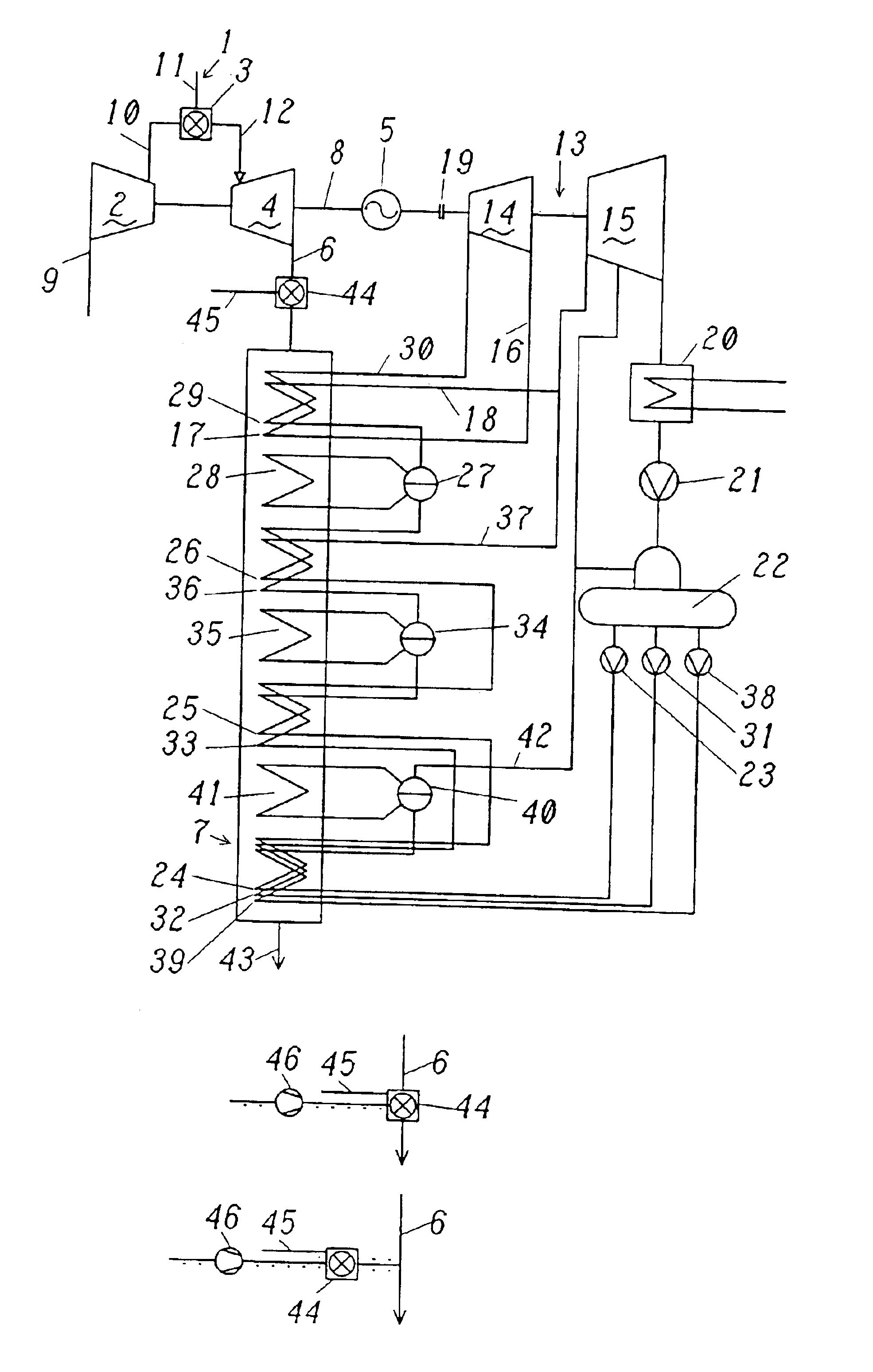
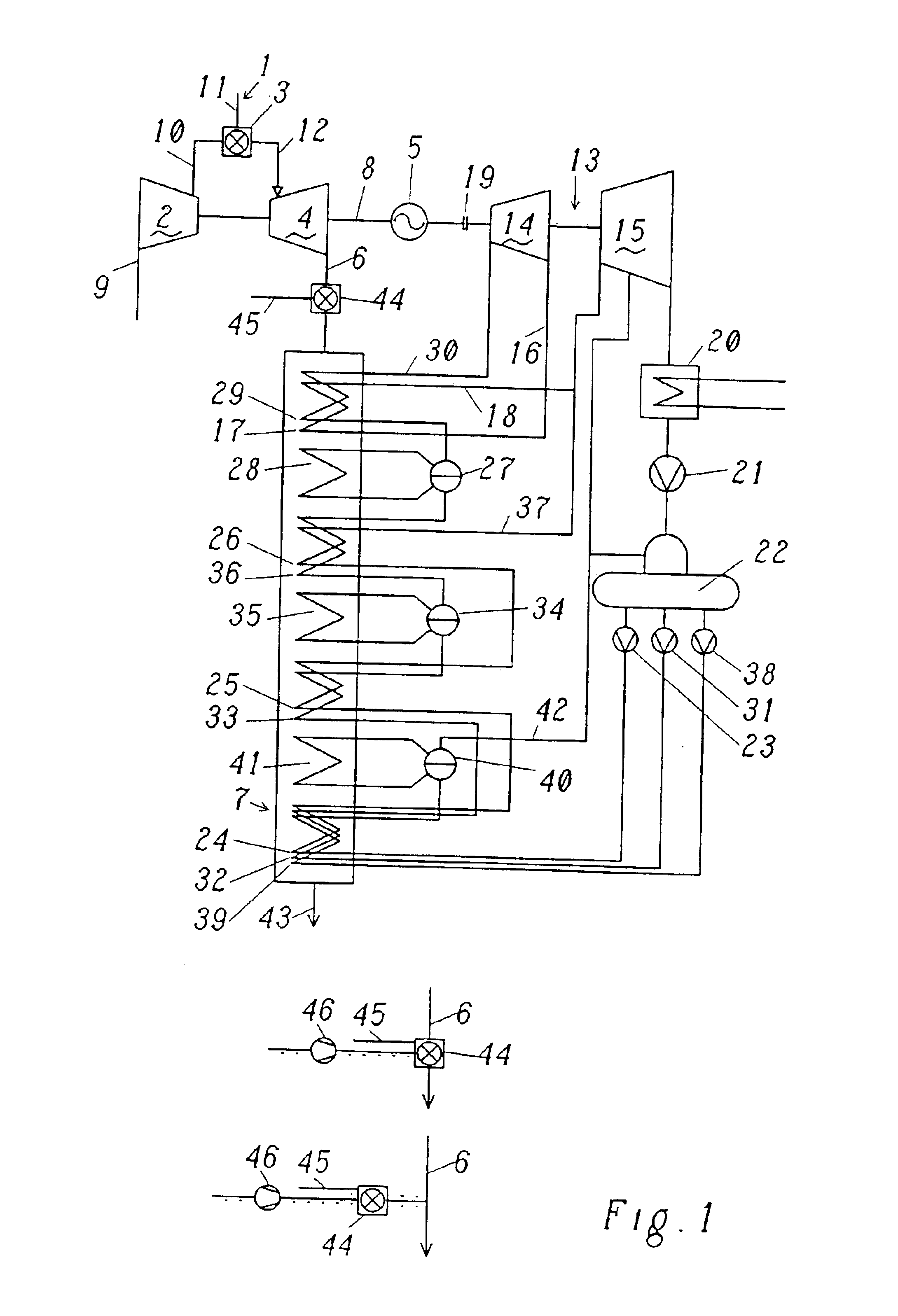
the method according to the invention is distinguished in that the temporary increase in the power output of the combined-cycle power station is provided solely via the supplemental firing and the steam turbo group, and in that the fuel supply to the gas turbo group is reduced to its original level again while the additional power output is being built up via the supplemental firing. This reduction in the output power from the gas turbo group to the original operating point as quickly as possible ensures that the gas turbo group is protected as much as possible, and is overloaded only to the minimum extent.

In a second embodiment of the method, the combined-cycle power station is a system in which the gas turbo group drives an electricity generator, and the combined-cycle power station has a steam turbo group with two or more steam turbines, in particular preferably with a high-pressure steam turbine and a medium-pressure or low-pressure steam turbine. The gas turbo group and the ste...


PUM


Abstract

In a method for increasing the power output of a combined-cycle power station, comprising at least one gas turbo group, at least one heat recovery steam generator and at least one steam turbo group, with the gas turbo group comprising at least one compressor, at least one combustion chamber and at least one gas turbine, the heat recovery steam generator having at least one pressure stage and the steam turbo group comprising at least one steam turbine, in which combined-cycle power station air is compressed in a compressor, is then supplied as combustion air to a combustion chamber, the hot gas which is produced there is passed to a gas turbine, and the exhaust gas from the gas turbine is used in a heat recovery steam generator to produce steam for a steam turbo group, an immediate and rapid increase in the power output is achieved, and an additional power output from the combined-cycle power station is maintained in safe operating conditions, in that an supplemental firing is arranged to provide additional heating for the exhaust gas from the gas turbine and in that the combustion chamber or the gas turbo group is supplied with more fuel, and the supplemental firing is switched on at the same time, for immediately, rapidly and temporarily increasing the power output of the combined-cycle power station, and in that the power output of the gas turbo group is reduced again to the extent that the additional steam power produced as a result of the supplemental firing is also provided via the steam turbo group as power.

Description

The present invention relates to a method for operating a combined-cycle power station. In particular, the invention relates to a method in which primary response and secondary response requirements are satisfied by a combined-cycle power station in a manner which protects the system, via the interaction of the thermal power from the fuel in the gas turbo group and an supplemental firing in the heat recovery steam generator.PRIOR ARTWith the liberalization of the energy markets, the competition is also becoming considerably more intense in the field of electricity supplies. This is leading on the one hand to rapid introduction of modern energy conversion methods, particularly those with very high efficiency. However, efforts are being made to look for more cost-effective options in the field of providing cold and hot reserves, as well. These requirements are satisfied to a major extent by gas turbo groups and combined-cycle power stations.Gas turbo groups are able to provide compara...

Claims


Application Information

Patent Timeline
Patent Type & Authority Patents(United States)
IPC IPC(8): F01K23/10
CPCF01K23/105F01K23/108Y02E20/16
Inventor LIEBIG, ERHARD
Owner ANSALDO ENERGIA IP UK LTD
Why Eureka
Try Eureka