
Plate handling method and apparatus for printing press

a plate handling and printing press technology, applied in printing, office printing, rotary letterpress machines, etc., can solve the problems of plate being removed by ink rollers and damage blankets or rollers, damage to printing plates of other printing units, and many man-hours and much time, so as to reduce the damage to plate cylinders, plate changing time, and the effect of reducing the number of plate cylinders

Inactive Publication Date: 2004-11-09
KOMORI CORP
View PDF7 Cites 7 Cited by
  • Summary
  • Abstract
  • Description
  • Claims
  • Application Information

AI Technical Summary

Benefits of technology

For example, Japanese Patent No. 2704558 discloses a method for changing plates in a printing press having a plurality of printing units different in the rotation phase of each plate cylinder, whereby even when plate removal in one of the printing units is taking place, a plate removal operation is performed in the other printing units, thus shortening the plate changing time.
The present invention has been conceived to solve the above problems. Its object is to provide a plate handling method and a plate handling apparatus for a printing press having a plurality of printing units, the method and the apparatus being constituted such that during a plate removal or plate supply operation for the erring unit where an abnormality in the plate removal or plate supply was detected, a plate removal or supply operation for the other normal units can be performed continuously, whereby the plate removal or supply can be carried out reliably in a short period of time.
and allowing the drive force from the drive device to remain transmitted in the other printing units, thereby continuing supply or removal of the plates in the other printing units.
According to the plate handling method and apparatus of the present invention, the drive force from the drive device to the printing unit, where an error (abnormality) during plate changing has occurred, is cut off, but a plate changing operation for the other printing units is continued. Thus, the plate changing time can be shortened, and damage to the plate, plate cylinder, and surrounding devices in the printing unit undergoing the error can be minimized.

Problems solved by technology

If an error occurs during the plate removal (or plate supply) operation by the automatic plate changer, the plate being removed may be caught by ink form rollers and damage a blanket or the roller, unless the plate changing procedure is promptly stopped.
Thus, damage may be caused to the printing plate of other printing unit where no abnormality in the plate removal was detected when the abnormality was detected.
To remove the damaged printing plate, many man-hours and much time are required.
Similar problems are posed when an abnormality in the plate being supplied occurs during a plate supply operation for automatically mounting printing plates on plate cylinders.

Method used


Image

  • Plate handling method and apparatus for printing press
  • Plate handling method and apparatus for printing press
  • Plate handling method and apparatus for printing press

Examples


embodiment

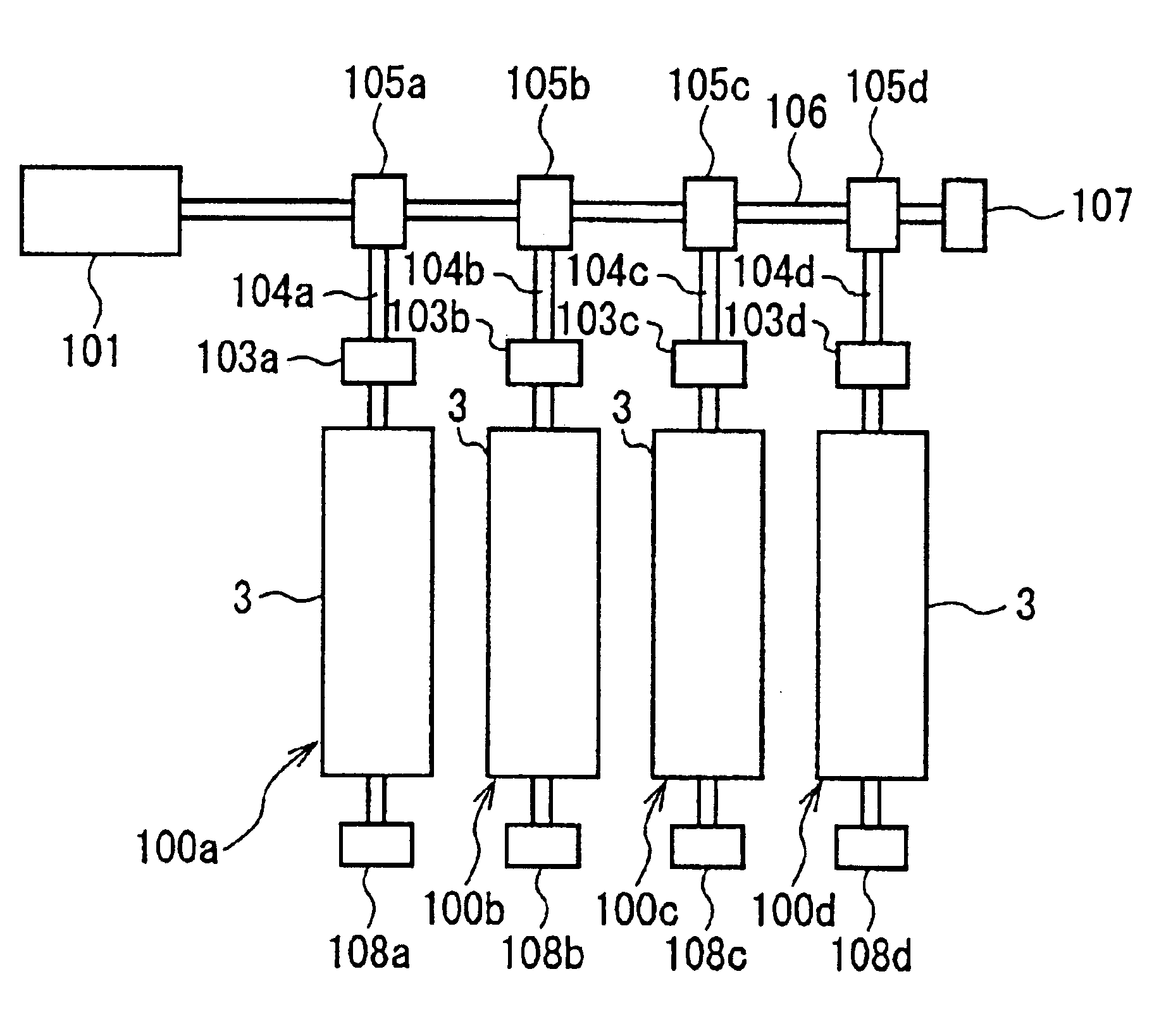
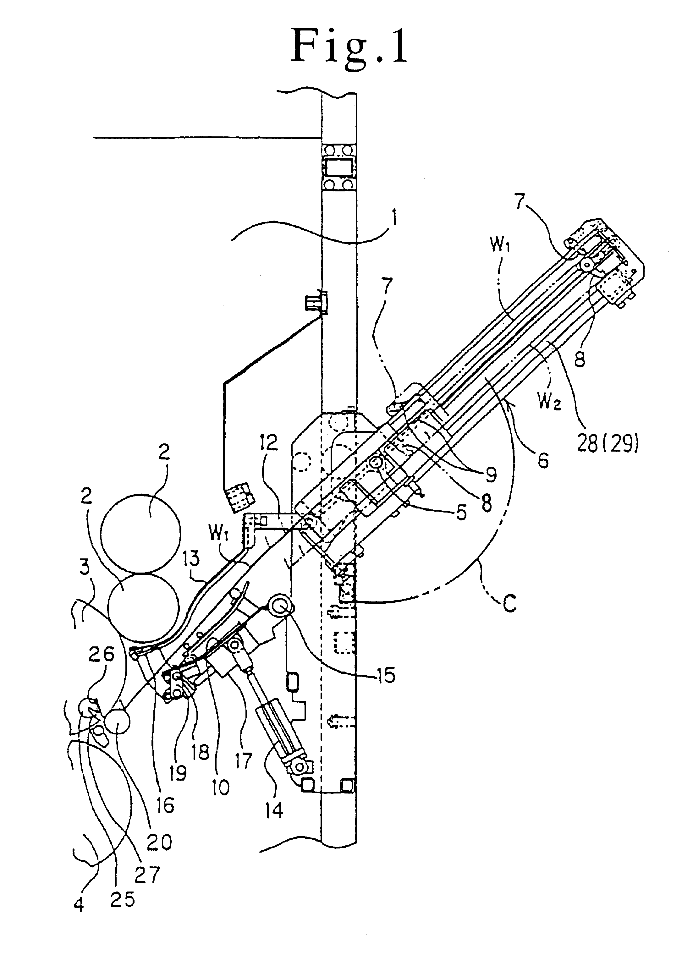
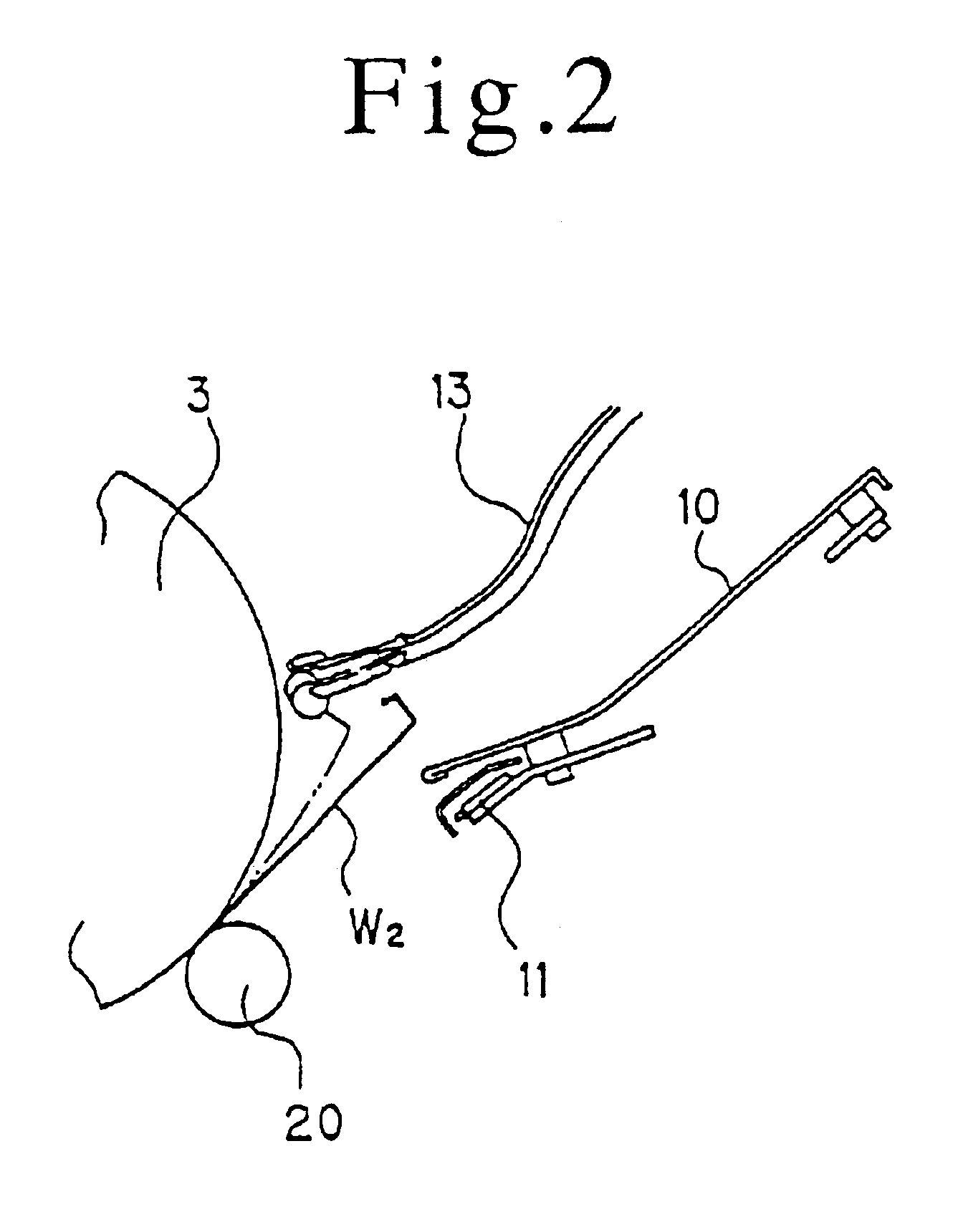
FIG. 1 is a schematic configuration drawing of an automatic plate changer and its surroundings showing an embodiment of the present invention. FIG. 2 is an enlarged view of a moving plate guide portion. FIG. 3 is an enlarged view of a plate gripping / extracting guide portion. FIG. 4 is an enlarged view of a plate press roller portion. FIG. 5 is a schematic block diagram of an entire perfecting printing press. FIG. 6 is a schematic configuration drawing of a drive system.

As shown in FIG. 1, ink rollers 2, a plate cylinder 3, and a blanket cylinder 4 of an upper printing section (upper printing unit) are rotatably supported between right and left frames 1 of a perfecting printing press, and a web O (as shown in FIG. 4) passing between the blanket cylinder 4 and a blanket cylinder 4 of a lower printing section (lower printing unit) is subjected to printing. The upper printing unit and the lower printing unit constitute a set, and a plurality of the sets are arranged in line in the direc...


PUM


Abstract

A plate handling method and apparatus for a printing press that includes printing units, each having a plate cylinder, a main unit motor for driving the plate cylinders, and electromagnetic clutches disposed between the main unit motor and the printing units for transmitting and cutting off a drive force from the main unit motor to the printing units, and is adapted to rotate the plate cylinders upon the drive by the main unit motor and change plates. The electromagnetic clutch of the printing unit is disengaged, when an abnormality in changing of the plate was detected by any of sensors provided in each printing unit for detecting an abnormality in plate changing, to cut off the drive by the main unit motor, but continue plate changing in the other printing units by the drive force from the main unit motor.

Description

The entire disclosure of Japanese Patent Application No. 2002-90987 filed on Mar. 28, 2002, including specification, claims, drawings and summary, is incorporated herein by reference in its entirety.1. Field of the InventionThis invention relates to a plate handling method and a plate handling apparatus for a plate cylinder of a printing press.2. Description of the Related ArtFor a web rotary press or the like, in which a plurality of printing units are arranged, various proposals have been made for an automatic plate changer, which automatically mounts a printing plate (hereinafter referred to simply as a plate) at a predetermined position of a plate cylinder of each of the plural printing units, and automatically removes the plate from the plate cylinder.For example, Japanese Patent No. 2704558 discloses a method for changing plates in a printing press having a plurality of printing units different in the rotation phase of each plate cylinder, whereby even when plate removal in on...

Claims


Application Information

Patent Timeline
IPC IPC(8): B41F27/12B41F33/14
CPCB41F33/14B41F27/1206
Inventor TOBE, KENJITAKEDA, KAZUNORI
Owner KOMORI CORP
Learn More