Machine for drying, polishing and burnishing cutlery and metal tableware

a technology for burningishing machines and cutlery, which is applied in the direction of grinding machines, applications, household cleaners, etc., can solve the problems of difficulty in regularly advancing along the channel, detriment to the machine's functionality and efficiency, and inability to completely eliminate the drawbacks of the said machine, so as to improve the effectiveness of treatment and reduce noise.

Inactive Publication Date: 2004-11-09
HYPPOCAMPUS
View PDF4 Cites 35 Cited by
  • Summary
  • Abstract
  • Description
  • Claims
  • Application Information

AI Technical Summary

Benefits of technology

In fact, one of the objects of this invention is to make and supply a machine for drying, polishing and burnishing metal tableware with an improved shape, operation and inclination of the channel that the drying material and articles have to climb, improving the efficiency and reliability of the machine and the effectiveness of the treatment.
Thus, the channel is freed of sharp bends and corners that may block the advance of the articles during the treatment phase. Thanks to the concave bottom, furthermore, the articles tend to remain and return to the lowest part of said bottom, at the centre of the channel, immersed in the drying material, without ever ending up crossways, bumping against the walls and becoming stuck, even when following the curves that mark a change in direction. Consequently, the machine is less noisy, even though it has no plastic protective lining along the channel surfaces.
Another benefit lies in the fact that the treatment channel has a variable inclination, with a steeper gradient towards the exit passage or chute. This means that the drying material and the articles advance more slowly, at least in the final part of the channel, in order to improve the effectiveness of the treatment and to favour the separation of the drying material from the articles when they reach a grill at the end.

Problems solved by technology

Said machine, however, is not completely free of drawbacks.
In fact, on account of the shape of the treatment channel, the articles being treated come to rest on the flat bottom and have difficulty in advancing regularly up along the channel.
These difficulties are added to by the fact that the articles tend to end up crosswise in the channel, becoming blocked against the side walls.
This is at the detriment of the machine's functionality and efficiency, with the further disadvantage of making the machine very noisy, as the pieces bump against the channel walls.

Method used


Image

  • Machine for drying, polishing and burnishing cutlery and metal tableware
  • Machine for drying, polishing and burnishing cutlery and metal tableware
  • Machine for drying, polishing and burnishing cutlery and metal tableware

Examples


Embodiment Construction

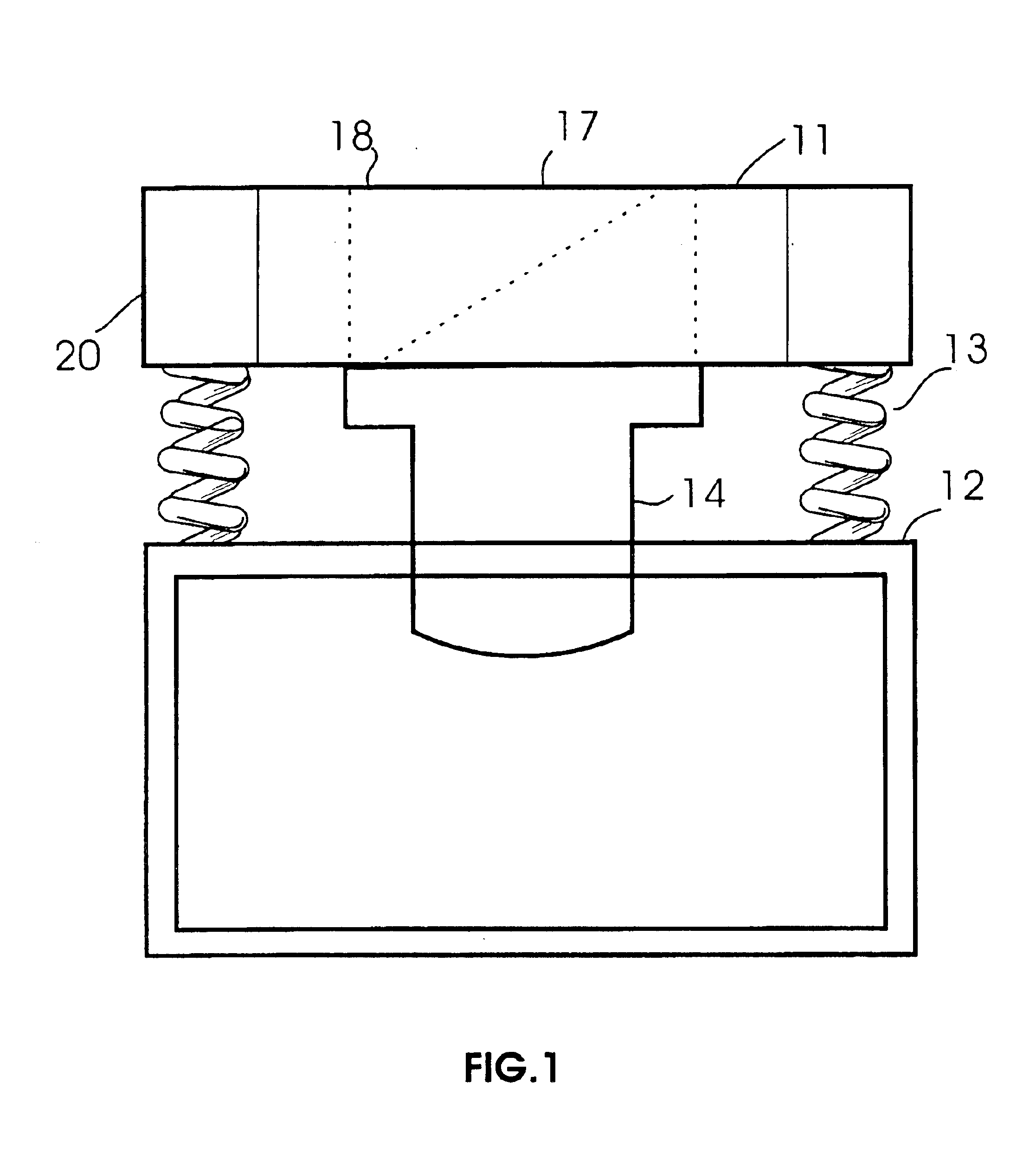
The machine of the invention consists essentially of a tank 11 suspended over a base 12 with springs 13 between them, associated with a motor-driven vibrator 14, which keeps the whole in vibration during operation.

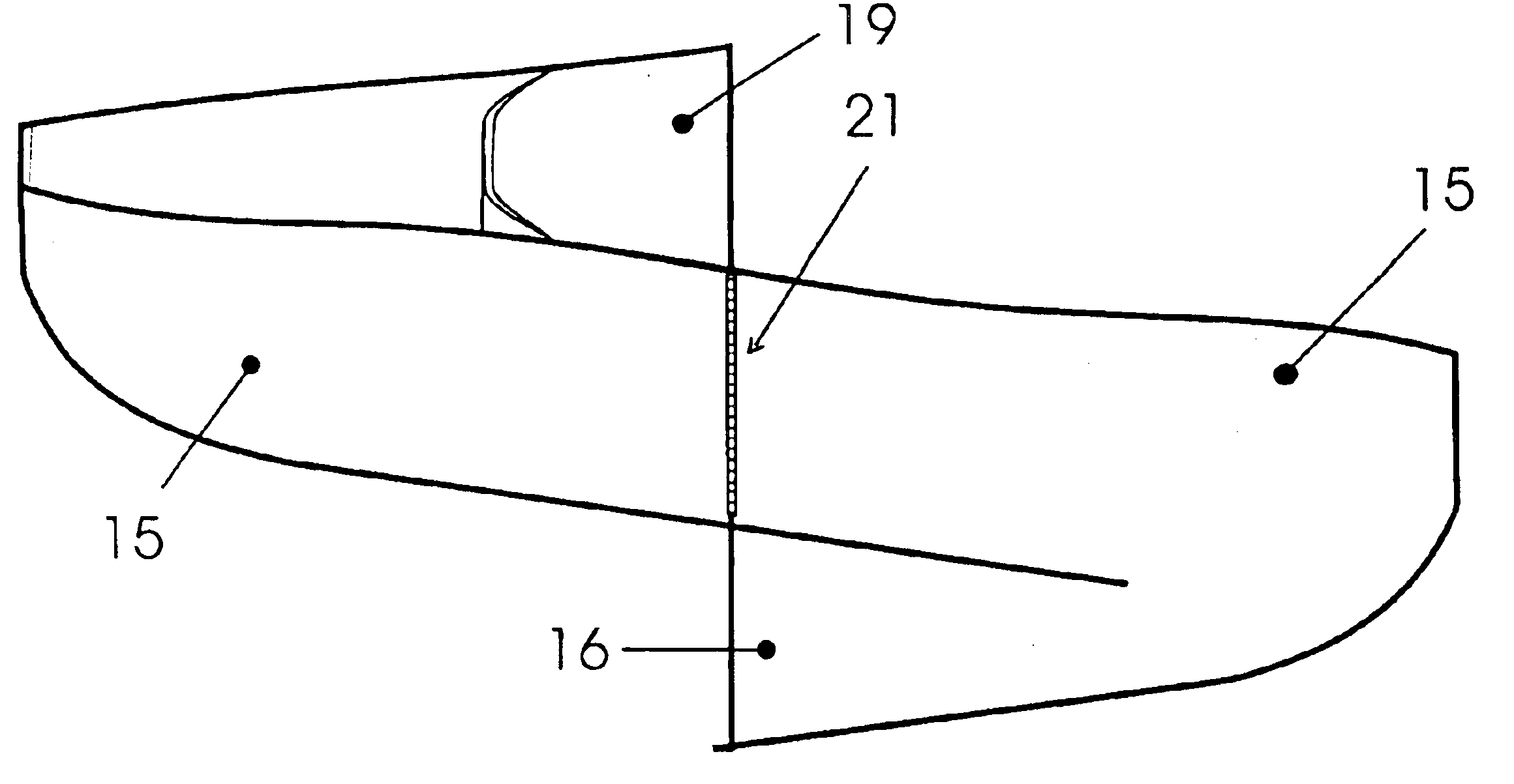
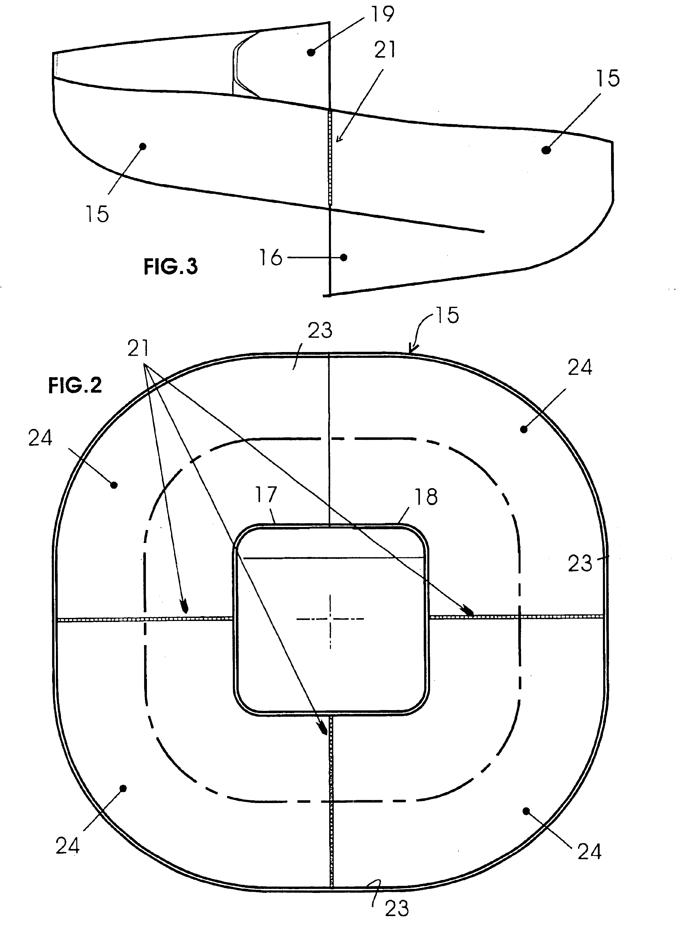
The tank 11 contains a treatment channel 15, designed to receive the drying material as well as the articles for treating. The drying material may be a granulation of corn shavings, or another suitable product that also performs the polishing and burnishing.

The channel 15 has a spiral shape which rises from a lower part 16, where the articles for treatment are delivered by means of a chute 17, located in a central loading mouth 18, up to a higher part 19, where the articles are unloaded outside the tank, by means of an exit passage or chute 20, while the drying material is separated from the articles, falling through a grill, as already used elsewhere.

The channel 15 is defined by a body in stainless steel, consisting of complementary elements made in a die and subsequently...


PUM


Abstract

This invention concerns a machine for the drying, polishing and burnishing cutlery and other metal tableware. It consists of a tank suspended upon a base and moved by a vibrating device, having a treatment channel (15) designed to receive a drying material and the articles for treatment. The treatment channel (15) rises in a spiral from an entrance chute at the loading mouth to an exit passage or chute for the articles and has, in a transverse cross-section, a U-shaped bottom (22) defined by a substantially cylindrical concave surface and, lengthways, by a series of straight segments (23) which alternate with and are joined to curved segments (24), without sharp edges or corners. Ideally, the channel has a steeper gradient towards the exit.

Description

This invention concerns machines for drying, polishing and burnishing cutlery and other metal tableware with the use of a treatment material, such as, for example, a granulation of corn shavings.In restaurants, canteens, communities and similar, the dirty cutlery, plates, glasses, etc. are cleaned in the dishwasher, then dried with the aid of a drying material and finally heated to completely remove water.In a previous disclosure of the same applicant, corresponding to U.S. Pat. No. 6,110,020, there was a specific proposal for a machine that dries, polishes and burnishes cutlery and metal tableware, with the purpose of removing all traces of lime-scale, marks or stains from the surface and, thereby, polishing the metal.Such a machine has a vibrating tank in which there is a channel through which the drying material and the objects to be treated have to pass. The tank with the channel is generally made by welding metal sheets together and covering this with a protective plastic linin...

Claims


Application Information

Patent Timeline
Patent Type & Authority Patents(United States)
IPC IPC(8): A47L21/00A47L21/02A47L19/00B24B31/073
CPCA47L19/00B24B31/073A47L21/02
Inventor ROLFI, EMILIO
Owner HYPPOCAMPUS
Why Eureka
Try Eureka