Spring seat for a railway truck sideframe and method of making the same

a technology of railway truck and sideframe, which is applied in the direction of manufacturing tools, foundry patterns, foundry moulding apparatus, etc., can solve the problems of voids in the sand core, defects in the cast metal component, and problems during the manufacture of sand cores

Inactive Publication Date: 2004-11-30
AMSTED RAIL CO INC
View PDF15 Cites 6 Cited by
  • Summary
  • Abstract
  • Description
  • Claims
  • Application Information

AI Technical Summary

Benefits of technology

Certain aspects of an embodiment of the present invention relate to an improved cast metal sideframe for use in a railway car truck. The sideframe has a spring seat for supporting springs from a spring set. The sideframe is molded using a core that includes a portion for defining the exterior surface of the spring seat. The spring seat includes a plurality of aerodynamically-shaped spring retainers formed on the spring seat. The aerodynamic shape of the spring retainers reduces the tendency for voids to form in the sand cores that are used to cast the sideframe.

Problems solved by technology

Problems can arise during the manufacture of the sand cores that are used to form these prior spring seats and spring retainers.
These vertical faces cause the sand to swirl as it is blown into the mold, thereby creating voids in the sand core and corresponding defects in the cast metal component.

Method used


Image

  • Spring seat for a railway truck sideframe and method of making the same
  • Spring seat for a railway truck sideframe and method of making the same
  • Spring seat for a railway truck sideframe and method of making the same

Examples


Embodiment Construction

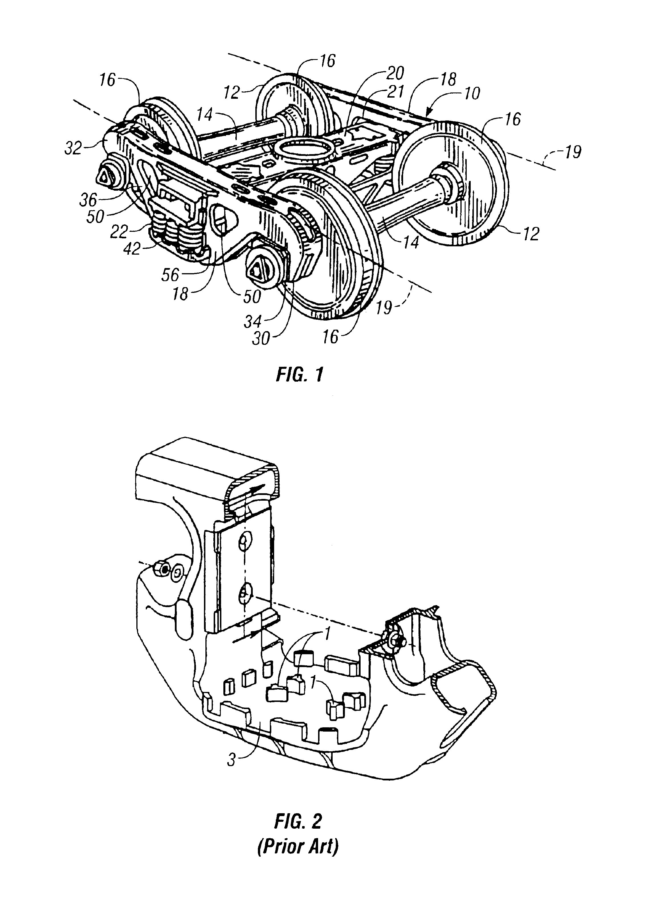
A railway truck 10 that may utilize a cast spring seat according to certain aspects of an embodiment of the present invention is illustrated in FIG. 1. Except as explained below, the railway truck 10 may be constructed generally in accordance with the rail trucks described in U.S. Pat. No. 5,481,986, issued Jan. 9, 1996 to Spencer et al. and entitled "Lightweight Truck Side Frame" (the "'986 Patent) and U.S. Pat. No. 5,752,564, issued May 19, 1998 to Callahan et al. and entitled "Railway Truck Castings and Method and Cores for Making Castings" (the "'564 Patent"). The disclosures of the '986 patent and the '564 patent are hereby incorporated by reference herein in their entirety.

As is shown in FIG. 1, a typical railway truck 10 includes a pair of wheelsets 12. Each wheel set 12 has an axle 14 with wheels 16 at the ends of each axle 14. The two wheelsets 12 support a pair of spaced, parallel sideframes 18. The two sideframes 18 have longitudinal centerlines 19 and are spanned by a bo...


PUM

PropertyMeasurementUnit
anglesaaaaaaaaaa
angleaaaaaaaaaa
obtuse angleaaaaaaaaaa

Abstract

A cast metal sideframe for use in a railway car truck has a spring seat for supporting the springs of a spring set. The sideframe is molded using a core that includes a portion for defining the exterior surface of the spring seat. The core can be a single piece or multi-piece core. The spring seat includes a plurality of aerodynamically-shaped spring retainers formed on the top face spring seat. The aerodynamic shape of the spring retainers reduces the tendency for sand to swirl and create voids during formation of the sand core that is used to mold the sideframe. The aerodynamic shape may include forming at least some of the side walls of the spring retainers at an obtuse angle with the top face of the spring seat. The spring retainers may have concave top faces so as to reduce the volume of material comprising the spring retainers. Reducing material volume is beneficial for reducing shrinkage during cooling of the sideframe, thereby reducing the tendency for separation, tears and cracks to form on the top surface of the spring retainer.

Description

FEDERALLY SPONSORED RESEARCH OR DEVELOPMENT[Not Applicable]MICROFICHE / COPYRIGHT REFERENCE[Not Applicable]BACKGROUND OF THE INVENTIONRailway freight car trucks are usually configured in a three-piece arrangement consisting of a pair of laterally spaced sideframes, a bolster extending between the sideframes, and a pair of wheel sets located at opposite ends of the sideframes. Each sideframe includes a centrally located bolster opening for receiving the end of a bolster that extends laterally between and perpendicular to the sideframes. The ends of the sideframes are laterally aligned to receive an axle wheel set in what is usually termed the pedestal jaw of the sideframe. Examples of typical railway trucks are shown in U.S. Pat. Nos. 4,363,276; 4,838,174; 5,718,177; and 6,125,767.A typical sideframe is comprised of an elongated top compression member that extends in a longitudinal direction parallel to the railway track. The sideframe also comprises two diagonally extending tension me...

Claims


Application Information

Patent Timeline
Patent Type & Authority Patents(United States)
IPC IPC(8): B61F5/52B61F5/00
CPCB61F5/52B22C9/02B22C9/103B22C9/108B22C9/22B22C21/14B22D25/02
Inventor BERG, THOMAS R.BAUER, ANTHONY J.CALLAHAN, THOMAS R.CHAIDEZ, HECTORSCHORR, RALPH H.
Owner AMSTED RAIL CO INC
Why Eureka
Try Eureka