Device for controlling the pitch of the blades of a convertible aircraft rotor

a technology for aircraft rotors and blades, which is applied in the direction of rotors, aircrafts, vertical landing/take-off aircrafts, etc., can solve the problem that the pitch change lever cannot be positioned to satisfy the needs of the user

Inactive Publication Date: 2004-11-30
EUROCOPTER
View PDF9 Cites 22 Cited by
  • Summary
  • Abstract
  • Description
  • Claims
  • Application Information

AI Technical Summary

Benefits of technology

In an advantageously simple form of structural embodiment, the bellcrank is substantially L-shaped, hinged at the elbow to the pitch control rod, at one end of one of its arms to the drive plate, and at one end of its other arm to the link rod. The overall size of the bellcrank is thus limited, while allowing satisfactory positioning of the pitch control rod and link rod hinges on the bellcrank, and of the latter on the drive plate, so as to obtain the slight inclination desired of the link rod to the radial plane, and therefore the desired delta-3 relation.
The link rod may thus, for different flapping values, and as a function of the pitch of the corresponding blade, exhibit a change in its inclination relative to any radial plane relative to the axis of the mast which has the effect that this inclination, the slope of which with respect to the radial plane (relative to the axis of the mast) has an effect on the delta-3 relation obtained, remains within a limited range of angular values, less than 20.degree., for a pitch range extending substantially from -10.degree. to 60.degree., and flapping values varying from -11.degree. to +11.degree..
This slight inclination of the link rod to any radial plane relative to the axis of the mast, and in a substantially transverse direction relative to the direction of the axis of the mast, is also favourable in terms of size, as well as in terms of final adjustments, since easily implemented changes in the positions of the bellcrank and the link rod, and in particular of their hinges to each other, and also to the pitch change lever for the link rod, and to the pitch control rod and the drive plate, for the bellcrank, make it easy to test different configurations of the pitch-flap relation, in order to obtain the desired delta-3 value by appropriate inclination of the link rod.
Also advantageously, to keep a small delta-3 value with low eccentricity and any number of blades, the pitch change lever projects towards the base of the mast at a radially inner end, relative to the axis of the mast, of a blade cuff, rigid in torsion and connected in torsion to the root of the corresponding blade about the pitch change axis, and surrounding said coupling for retaining and hingeing said blade in pitch. In this way, the pitch control takes place close to the hub and to the axis of the mast, and this pitch control device is directly compatible, because of the presence of the cuffs, with rotor hubs of the type with a plate in the form of a star comprising as many outward-extending arms as the rotor has blades, each arm of the hub supporting the coupling for retaining and hingeing a corresponding blade in pitch, these hubs being known for providing good rigidity in drag while exhibiting low rigidity in flapping, by the bending of the arms of the hub perpendicularly to their plane.

Problems solved by technology

On the other hand, on a rotor equipped with at least four blades, the flapping axis of a blade corresponds substantially with the longitudinal axis of the following blade, so that for reasons of geometry and interference the pitch change levers cannot be positioned to satisfy the above conditions.

Method used


Image

  • Device for controlling the pitch of the blades of a convertible aircraft rotor
  • Device for controlling the pitch of the blades of a convertible aircraft rotor
  • Device for controlling the pitch of the blades of a convertible aircraft rotor

Examples


Embodiment Construction

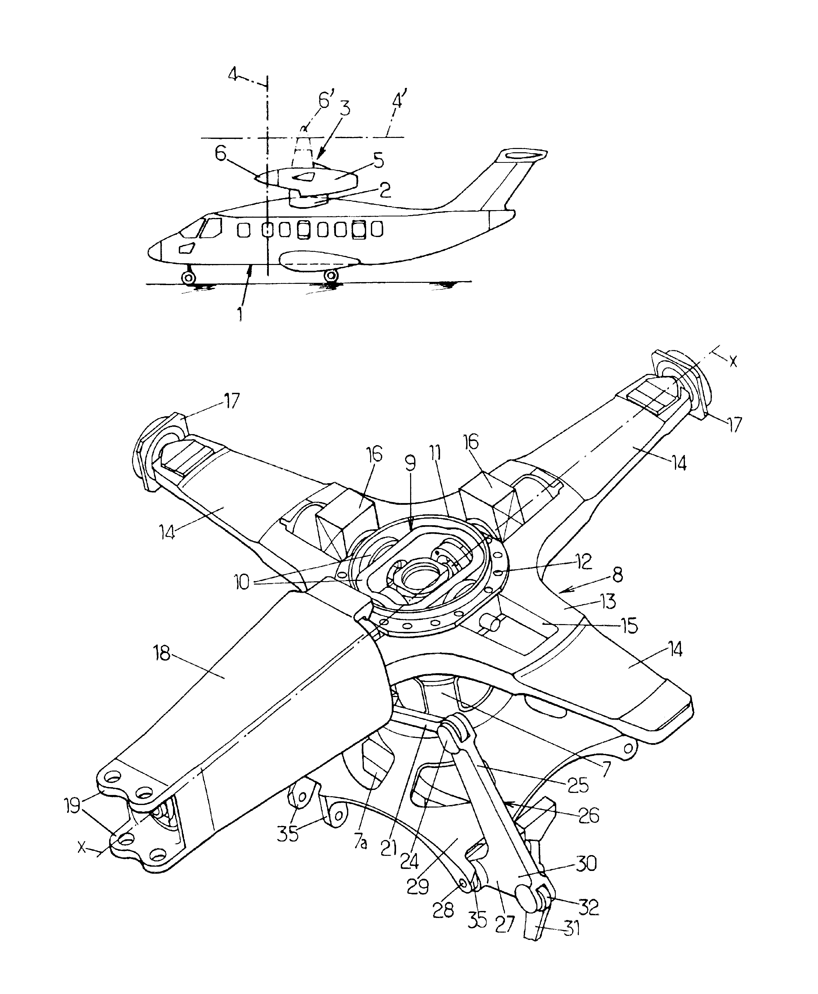
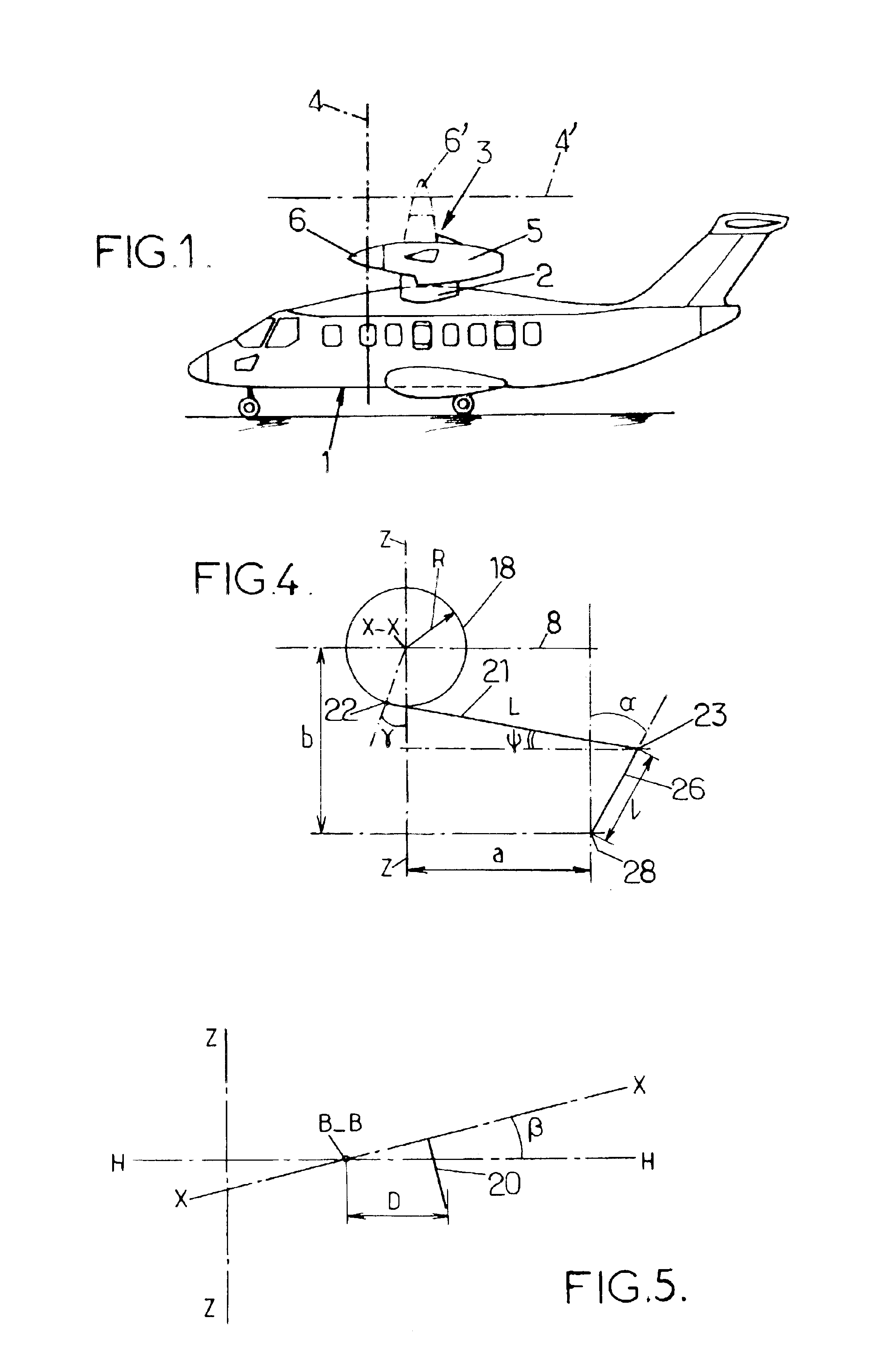
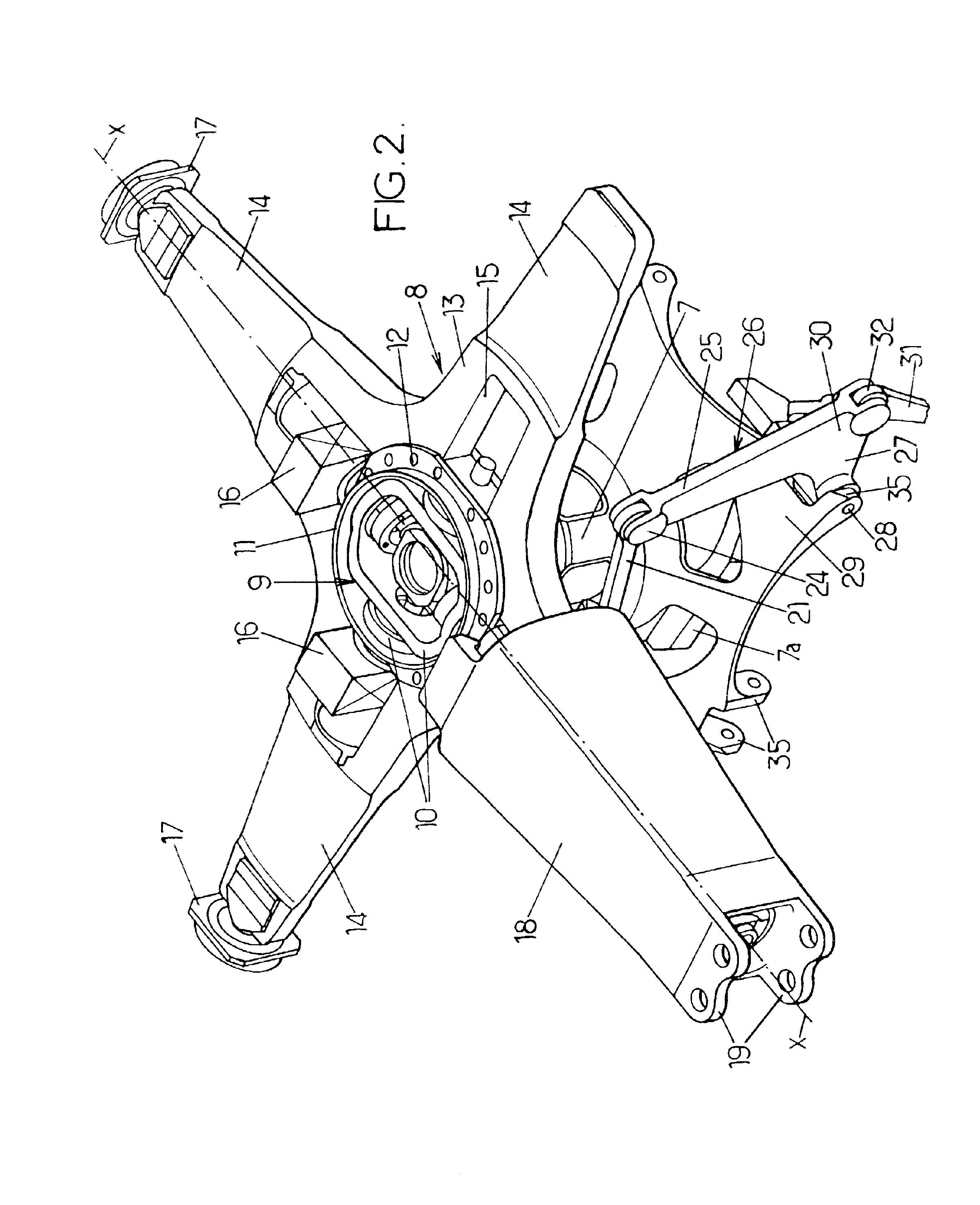
The four-bladed rotor head in FIGS. 2 and 3, for fitting to a tilting rotor 4 of a convertible aircraft according to FIG. 1, comprises a rotor mast 7, driven in rotation by its base 7a about its longitudinal axis Z--Z, and on which the opposite axial end to the base 7a is connected to a hub 8 by a device 9 providing constant velocity drive and tilting as a whole about any flapping axis intersecting the axis Z--Z and perpendicular to the latter, and which may extend in any direction about the axis Z--Z, this constant velocity drive and tilting device 9 being, for example, a double-gimbal device as described in U.S. Pat. No. 6,695,259; housed in a hub casing 11 attached by a ring of axial screws 12 to a hub plate 13.

In outline, this double-gimbal device 10 comprises two gimbals each mounted so as to pivot about one respectively of two diametral drive arms of the mast 7, perpendicular to each other and to the axis Z--Z, and each of which drives the corresponding gimbal in rotation abou...


PUM


Abstract

A pitch control device for a blade of a tilting rotor of a convertible aircraft. The pitch control device is external to a rotor hub which is driven in rotation by a mast and connected to the latter by a mechanism for tilting the hub as a whole, each blade is connected to the hub by a coupling for retaining and hingeing the blade in pitch about its pitch change axis. The device includes a pitch change lever, integral in rotation with its blade root about its axis, a pitch control rod, a bellcrank pivoting about a pin on a drive plate integral in rotation with the mast, and to which the pitch control rod is hinged, the bellcrank being also hinged to a link rod connected to the pitch change lever.

Description

The invention relates to a device for controlling the pitch of the blades of a convertible aircraft rotor of the known type supporting at least two wings, generally fixed, and at least one tilting rotor.A particularly advantageous application of the pitch control device according to the invention consists in fitting it to constant velocity drive tilting rotors for convertible aircraft, particularly of the type known and described in U.S. Pat. Nos. 6,276,633, 6,260,793 and 6,607,161 to which reference may advantageously be made for further details.Briefly, such a convertible aircraft with tilting rotors generally comprises, as shown schematically in FIG. 1, a fuselage 1, of the aircraft fuselage type, supporting two fixed wings 2, for example high wings, raised with respect to the fuselage 1, each wing 2 itself supporting a power pod 3, housing a power unit driving in rotation a rotor 4, represented schematically by the plane of rotation of the rotor blades, via a transmission (not s...

Claims


Application Information

Patent Timeline
Patent Type & Authority Patents(United States)
IPC IPC(8): B64C27/32B64C27/00B64C27/605B64C29/00B64C27/28B64C27/41
CPCB64C27/28B64C29/0033B64C27/605B64C27/41
Inventor ZOPPITELLI, ELIORAMPAL, ETIENNECORNILLE, ERIC
Owner EUROCOPTER
Why Eureka
Try Eureka