Vacuum pneumatic system for conveyance of ice

a pneumatic conveyor and vacuum technology, applied in the direction of liquid transfer devices, packaging goods types, lighting and heating apparatus, etc., can solve the problems of affecting the service of drive-up and counter patrons, and often not getting periodic manual refilling of ice bins

Inactive Publication Date: 2004-12-07
TEK SOLUTIONS
View PDF90 Cites 92 Cited by
  • Summary
  • Abstract
  • Description
  • Claims
  • Application Information

AI Technical Summary

Problems solved by technology

Such beverage and ice dispensing machines do not normally manufacture ice.
When this happens with a patron-area dispenser the patrons will be understandably annoyed.
When it happens with a dispenser used by the serving staff, service to drive-up and counter patrons will be impeded and such patrons will become annoyed by having to wait for long periods of time to receive their beverages.
However, for many reasons such periodic manual refilling of the ice bins often does not get accomplished; the assigned employee may be busy at other tasks or may be forgetful, the restaurant may be especially crowded and busy, patrons may be dispensing ice in larger quantities or more rapidly than anticipated, and so forth.
Whatever the cause, the failure of the restaurant to provide adequate quantities of ice upon patrons' demand is a constant and real source of customer dissatisfaction.
However, since a number of such ice makers are needed to server guests throughout the facility, the overall cost is high.
However, because the number of machines is kept to a minimum, many guests find that the location of the closest ice machine is inconvenient to their rooms.
Conversely, those whose rooms are close to the ice making machines frequently complain about the traffic and noise associated with other guests coming to obtain ice.
However, because of the minimum number of machines, frequently hospital staff find that they must walk long distances to obtain ice from the closest vending

Method used


Image

  • Vacuum pneumatic system for conveyance of ice
  • Vacuum pneumatic system for conveyance of ice
  • Vacuum pneumatic system for conveyance of ice

Examples


Embodiment Construction

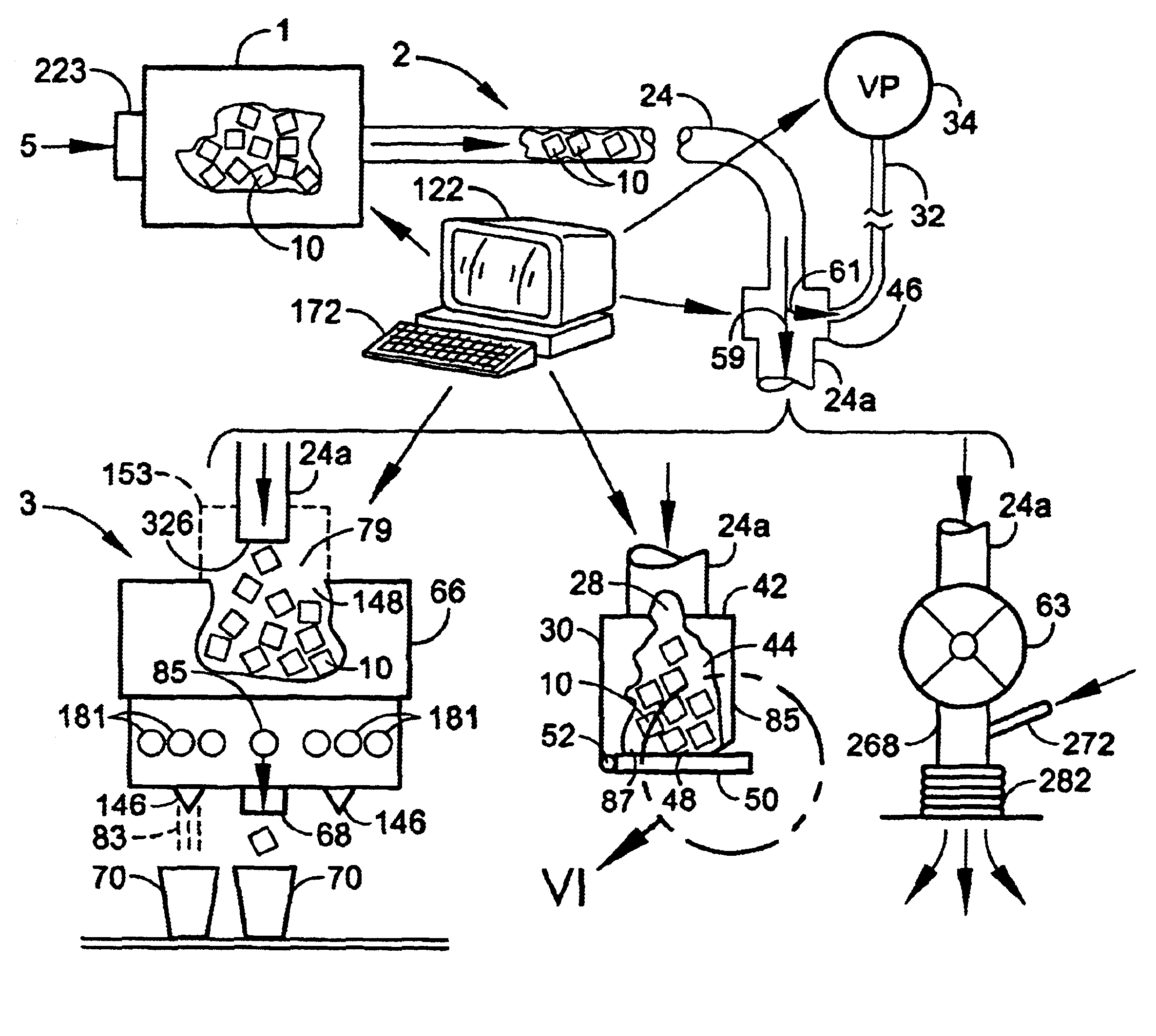
For brevity herein, the "pieces" of ice which are conveyed will frequently be exemplified and referred to simply as "ice cubes." It will be understood, however, that the term "ice cubes" is not to be restricted solely to ice pieces of essentially cubical shape, but will include ice pieces which have other substantially regular shapes such as half moons, crescents, cylinders, disks and various solid polygons. It is also intended to include pieces with irregular shapes, such as those formed by crushing, fragmenting, chipping or otherwise comminuting large solid blocks of ice into such irregular shapes. Ice which may be conveyed by this systems includes those ice products commonly known as "cube ice" (the above mentioned "ice cubes:), "nugget ice," "bridged ice," "granular ice," "chunk ice" and "crushed ice," or any other form or size of vacuum pneumatically conveyable ice pieces, regardless of the name applied.

Further for brevity, the conveying gas will be exemplified by air, which wi...


PUM

PropertyMeasurementUnit
Pressureaaaaaaaaaa
Angleaaaaaaaaaa
Lengthaaaaaaaaaa

Abstract

Vacuum pneumatic conveying apparatus and method are described to provide for a simple, economical, convenient (and preferably automatic) system for conveying ice on an as-required basis from a source such as an ice maker to one or more receptors at locations remote from that source. The system can be configured such that dispensing locations can be added or eliminated from the system or temporarily taken "off line" from the system without the need to change the basic system configuration or the central ice providing apparatus. The apparatus in various embodiments includes an ice source, a conveying conduit from the source to the receptor, a vacuum pump for moving the ice through the conduit by vacuum, and the receptor to collect the conveyed ice. The receptor may be an ice/beverage dispenser, an accumulator for retention and discharge to further devices, an intermediate storage dispenser, or an air lock device from where the ice can be projected over significant distances. Ice and vacuum may simultaneously be routed into different branched routes, utilizing a unique diverter/air shifter with the capability of providing routing to up to four different routes. Appropriate sensors and controllers, which may be microprocessor-based, may be used to automate the system. The entire system is easily cleanable. The system is advantageously used by restaurants, groceries, hotels and motels, hospitals, laboratories, and many other establishments where the providing of ice at various locations is desirable or required.

Description

1. Field of the InventionThe invention herein relates to pneumatic conveyor systems. More particularly it relates to a vacuum pneumatic conveyor system for the rapid and efficient conveyance of ice.2. Description of the Prior ArtIn many commercial establishments there are ice dispensers from which patrons, employees or both can collect ice pieces (such as ice cubes) for chilling beverages or for other purposes. Among the most common examples of such establishments are the "fast food" restaurants. In a typical fast food restaurant there will be a single large ice making machine in the kitchen area which manufactures large quantities of ice cubes. In the food serving area (behind the counter) and / or in the customer service area (in front of the counter) there will be at least one and usually several beverage and ice dispensing machines. Those behind the counter will be utilized by the serving staff to prepare iced beverages for window service to drive-up patrons or for counter service...

Claims


Application Information

Patent Timeline
IPC IPC(8): F25C5/00
CPCF25C5/002F25C5/20
Inventor BERGE, J. ERICSEAMARK, GLENN S.SCHOEDER, ALFRED A.MCCLURE, MARK A.GLIMN, DANIEL A.
Owner TEK SOLUTIONS
Why Eureka
Try Eureka