Semiconductor switching device with function for vibrating current, thereby shutting down over-current

a switching device and electromagnetic technology, applied in electronic switching, emergency protective arrangements for limiting excess voltage/current, pulse techniques, etc., can solve the problem that the overheat shutdown function cannot operate in the case of a small short-circuit current, the microcomputer control may have problems in responding to such over-current, and the thermal loss of the shunt resistor due to a large load current cannot be ignored

Inactive Publication Date: 2004-12-14
YAZAKI CORP
View PDF8 Cites 14 Cited by
  • Summary
  • Abstract
  • Description
  • Claims
  • Application Information

AI Technical Summary

Benefits of technology

a gate driving circuit for turning OFF the main FET by counting the counter. This makes it possible to shut down a current without the presence or absence of a transient component if a current exceeding a normal range flows a current on the load side.

Problems solved by technology

In recent years, there is a problem that the thermal loss of the shunt resistor due to a large load current cannot be ignored.
However, the overheat shutdown function does not operate in the case of a small short-circuit current, such as so called layer short, which includes an incomplete short circuit having a small degree of short-circuit resistance.
However, the microcomputer control may have problems in responding to such over-current.
Thus, a large package space is required.
Moreover, there is a problem that the equipment cost is increased by these comparatively expensive elements.
Thus, the detection of over-current is delayed, and the switching device or wire has been excessively heated.

Method used


Image

  • Semiconductor switching device with function for vibrating current, thereby shutting down over-current
  • Semiconductor switching device with function for vibrating current, thereby shutting down over-current
  • Semiconductor switching device with function for vibrating current, thereby shutting down over-current

Examples


first embodiment (

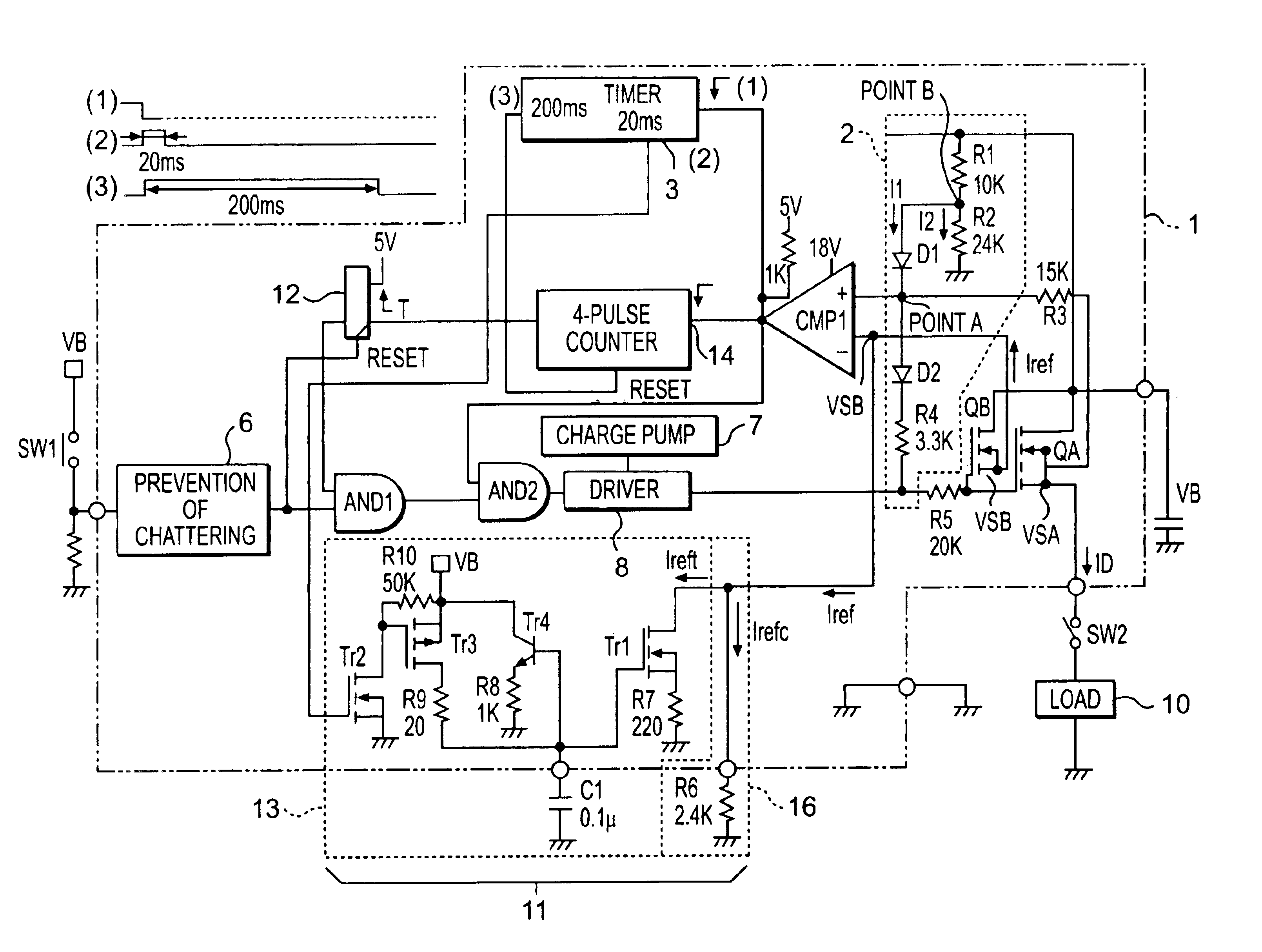
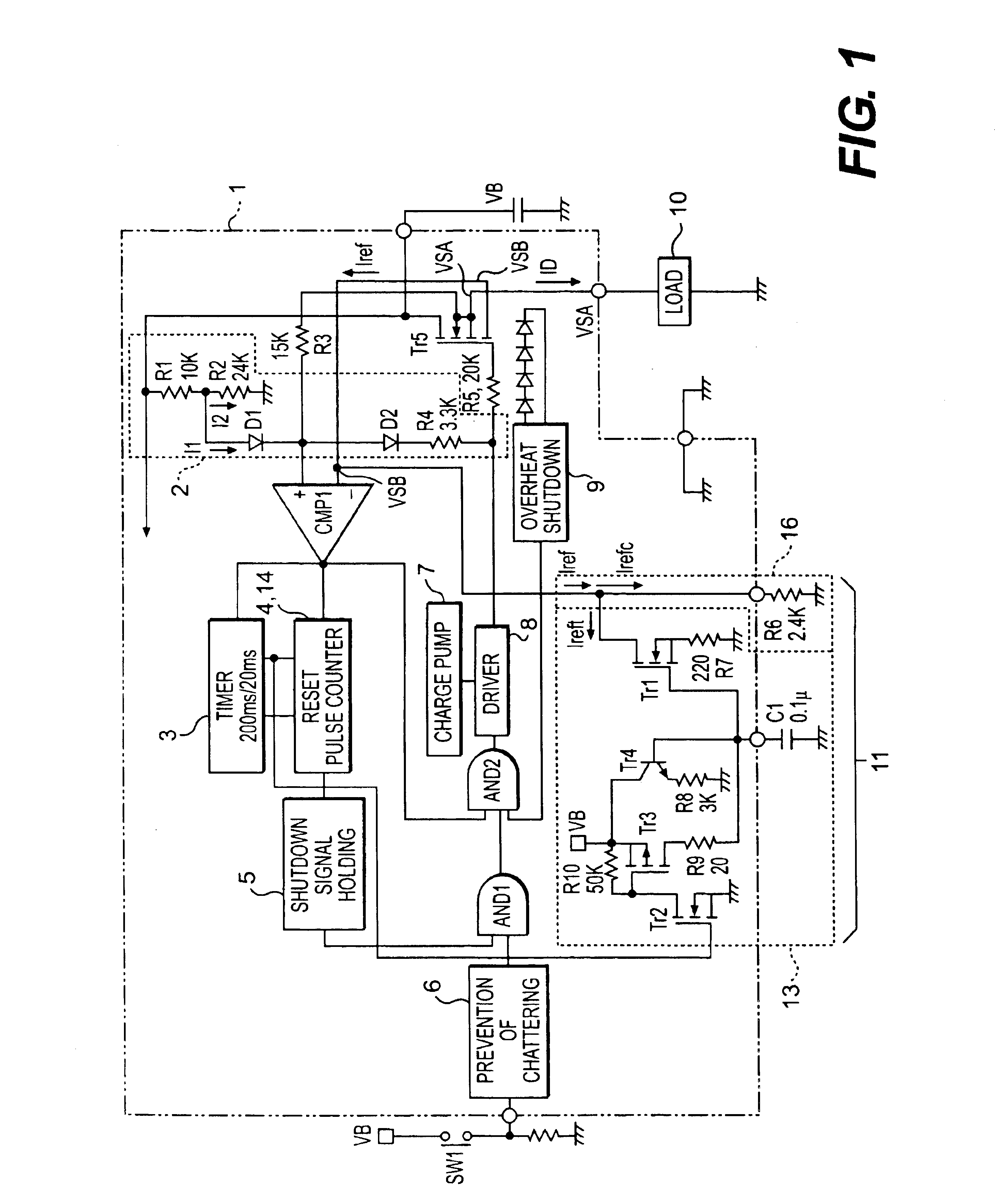
(First Embodiment (According to First Semiconductor Switching Device 1))

In the first embodiment, an operation of the first switching device 1 when a normal lamp load is used will be described here. A case in which a lamp does not function in a shutdown function, and continuously provides light is assumed. A lamp load 10is employed as a load having two 21W bulbs connected in parallel. FIG. 3 is a graph showing signal waveforms of a switching circuit 1 when the bulbs light. A lime of 50 milliseconds per scale is shown on a horizontal axis. On a vertical axis, there is shown a source potential (VSA) of the main FET (QA) of Tr5; and a voltage representing a timer output of 200 milliseconds output at an output terminal 3 until 200 milliseconds have been measured from the start of the timer 3; QA drain current ID; and drain current Iref of the reference FET (QB) of Tr5 obtained by "n" times. The unit of the vertical axis is shown at the right side of a respective one of VSA, ID, and Iref ...

second embodiment (

(Second Embodiment (According to First Semiconductor Switching Device 1))

In a second embodiment, a description will be given with respect to an operation of a first switching device 1 in the case where a lamp load is further added, and an overload state occurs when a normal lamp load lights. When the lamp lights, if an attempt is made to illuminate another lamp, the shutdown function works, and all the lamps are turned OFF. A lamp load having two 21W bulb lamps connected in parallel is used as a lamp load that initially lights. One 21W bulb lamp is used as an additional lamp load for overload, and is connected in parallel to two lighting lamps. FIG. 7 is a graph showing signal waveforms of a switching circuit until an overload has been added and shut down occurs when a bulb lights. A time of 20 milliseconds per scale is taken on the horizontal axis. VSA, input signal (gate driving signal) to driver 8, ID, and n.times.Iref are taken on the vertical axis. When n.times.Iref falls, n.ti...

third embodiment (

(Third Embodiment (According to First Semiconductor Switching Device 1)

In a third embodiment, a description will be given with respect to a first switching device 1 when a lamp load that is an overload is used. The lamp does not light because a shutdown function has operated. A lamp load 10 is employed as a load having three 21W bulb lamps connected in parallel. In the device 1, n.times.Iref is set so that overload is obtained by three lamps rather than two lamps. FIG. 11 is a graph showing signal waveforms of a switching circuit from driver input signal ON to shut down. A time of 100 microseconds per scale is taken on the horizontal axis. VSA, input signal, ID, and n.times.Iref are taken on the vertical axis. QA is shut down when eight ON / OFF operations are repeated. In a process in which ID and n.times.Iref is increased each time, a current ID that has been smaller than n.times.Iref is greater than n.times.Iref close to 35A. By this reversal, QA and QB are turned OFF. VSA and VSB ...


PUM


Abstract

A reference current (Iref) that includes a constant component current (Irefc) and a transient component current (Ireft) is fed to the reference FET (QB) such that a source potential (VSA) of the main FET (QA) when a load current (ID) flowing a main FET (QA) is not within the range of an over-current containing a transient component is not lower than a source potential (VSB) of a reference FET (QB). A reference current (Iref) vibrates by detecting that a source potential (VSA) of the main FET is lower than a source potential (VSB) of a reference FET. A vibration number of times is counted up to a predetermined number of times, thereby turning OFF the main FET (QA).

Description

The subject application claims benefit of the earlier filing dates of Japanese Patent Application Nos. 2000-222982 and 2000-363644 filed on Jul. 24, 2000 and Nov. 29, 2000 under the Paris Convention, the entire contents of which are incorporated by reference herein.1. Field of the InventionThe present invention relates to a semiconductor switching device for detecting and shutting down an over-current caused by current vibration. More particularly, the present invention relates to a semiconductor switching device capable of detecting an over-current even when a rush current supplies a load, such as a lamp load or a motor load.2. Description of the Related ArtA conventional semiconductor switching device (power semiconductor device) is employed for power supply control. The semiconductor switching device selectively supplies a battery power to respective loads in an automobile. The semiconductor switching device controls the power supply to a load by an incorporated thermal FET.The s...

Claims


Application Information

Patent Timeline
Patent Type & Authority Patents(United States)
IPC IPC(8): H03K17/082H02H1/00H02H1/04H02H3/087H03K17/08H02H3/093H03K17/687
CPCH03K17/0822H02H1/043H03K2017/0806H02H3/087H03K17/08
Inventor OHSHIMA, SHUNZOU
Owner YAZAKI CORP
Why Eureka
Try Eureka