
Sinusoidal frequency generator and periodic signal converter using thereof

a technology of sinusoidal frequency and converter, which is applied in the direction of oscillation generator, pulse automatic control, electric apparatus, etc., can solve the problems of increasing power consumption, increasing complexity, and difficult filtering

Inactive Publication Date: 2004-12-21
STMICROELECTRONICS SRL
View PDF7 Cites 4 Cited by
  • Summary
  • Abstract
  • Description
  • Claims
  • Application Information

AI Technical Summary

Benefits of technology

"The present invention provides a simple and inexpensive circuit for generating a sinusoidal signal. The circuit is based on a gyrator, which is an oscillator that can be controlled by a control voltage to produce a high-quality sinusoidal signal. The circuit is easy to implement, works in a broad frequency range, and can be easily incorporated into a semiconductor product. The technical effect of the invention is to provide a more efficient and cost-effective solution for generating a sinusoidal signal while maintaining its purity."

Problems solved by technology

On the other hand, the large amount of odd harmonics contained in the periodic square signal makes filtering particularly difficult and it is then necessary to use more filters and to increase their complexity to reach a low distortion rate in the generated sine wave.
Such complexity then results in a need for space on the semiconductor product, in an increased power consumption and finally in significantly high implementation costs.

Method used


Image

  • Sinusoidal frequency generator and periodic signal converter using thereof
  • Sinusoidal frequency generator and periodic signal converter using thereof
  • Sinusoidal frequency generator and periodic signal converter using thereof

Examples


Embodiment Construction

It should be understood that these embodiments are only examples of the many advantageous uses of the innovative teachings herein. In general, statements made in the specification of the present application do not necessarily limit any of the various claimed inventions. Moreover, some statements may apply to some inventive features but not to others. In general, unless otherwise indicated, singular elements may be in the plural and vice versa with no loss of generality. In the drawing like numerals refer to like parts through several views.

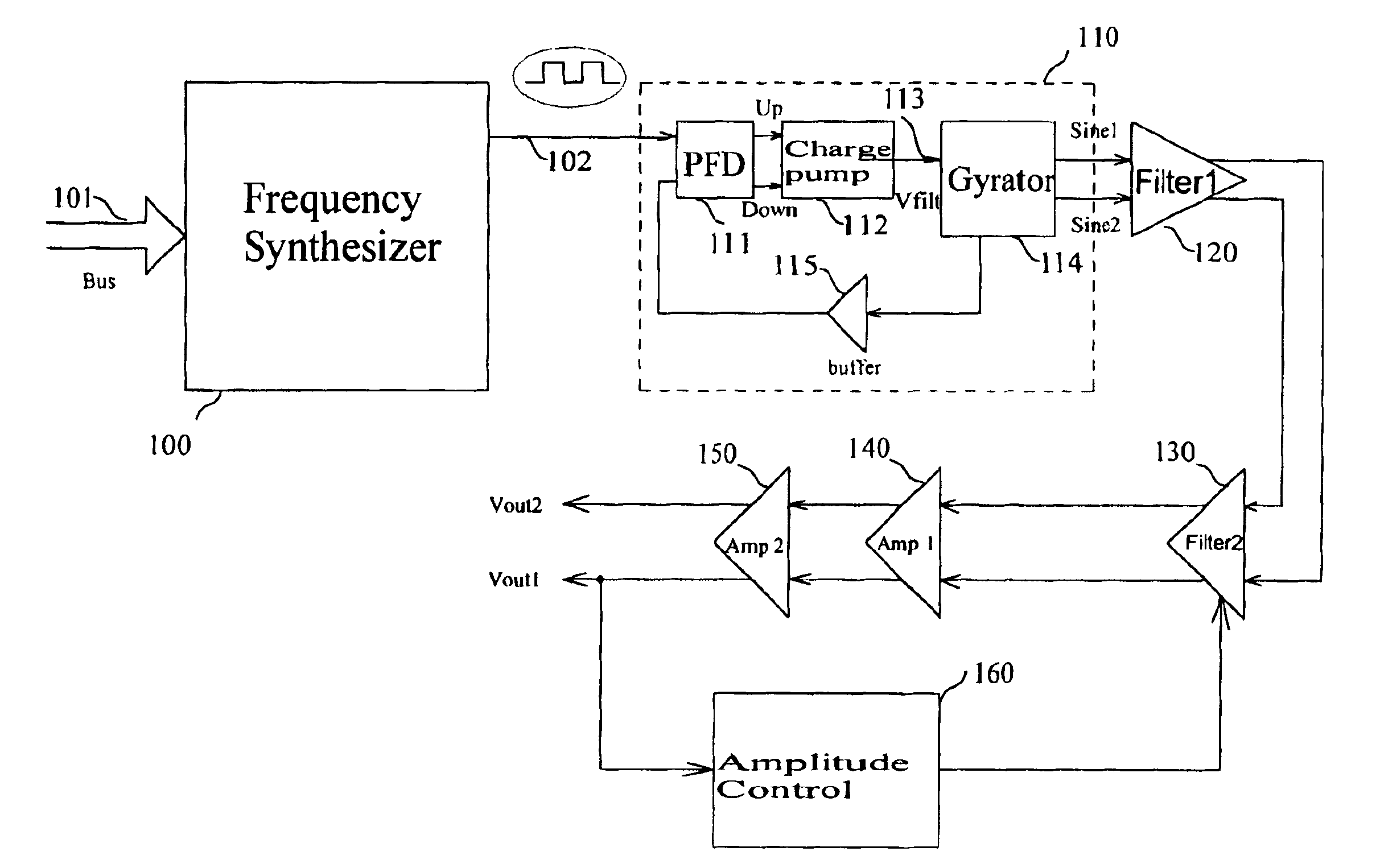
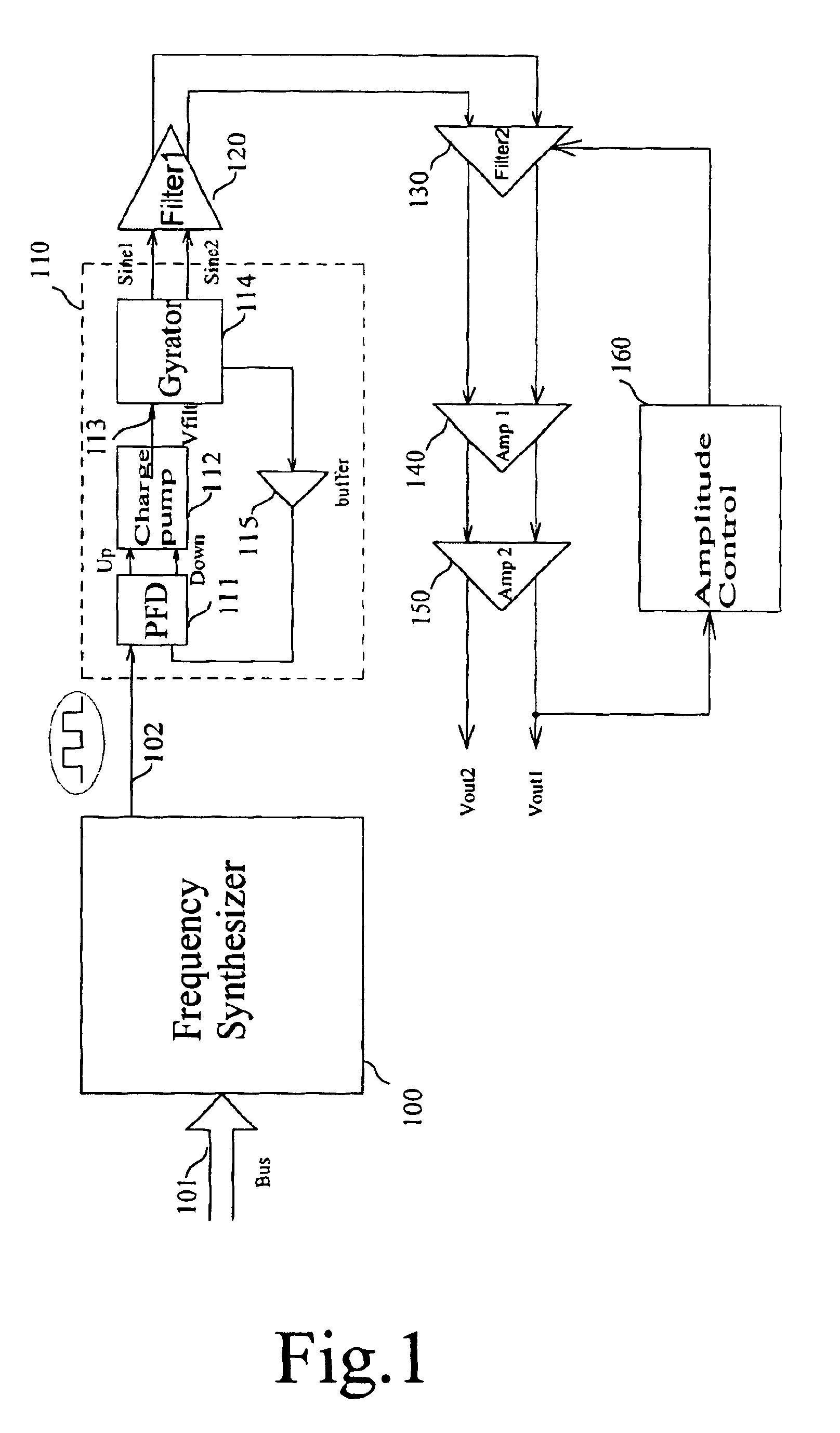
FIG. 1 is an electrical schematic of an embodiment of the digital signal converter, according to the present invention. A digital synthesizer 100 generates a periodic square signal 102 at a frequency that is determined according to the information presented to an input bus 101. Such a digital synthesizer is known to those of average skill in the art and need not be further described to understand the teachings of the present invention. The frequen...


PUM


Abstract

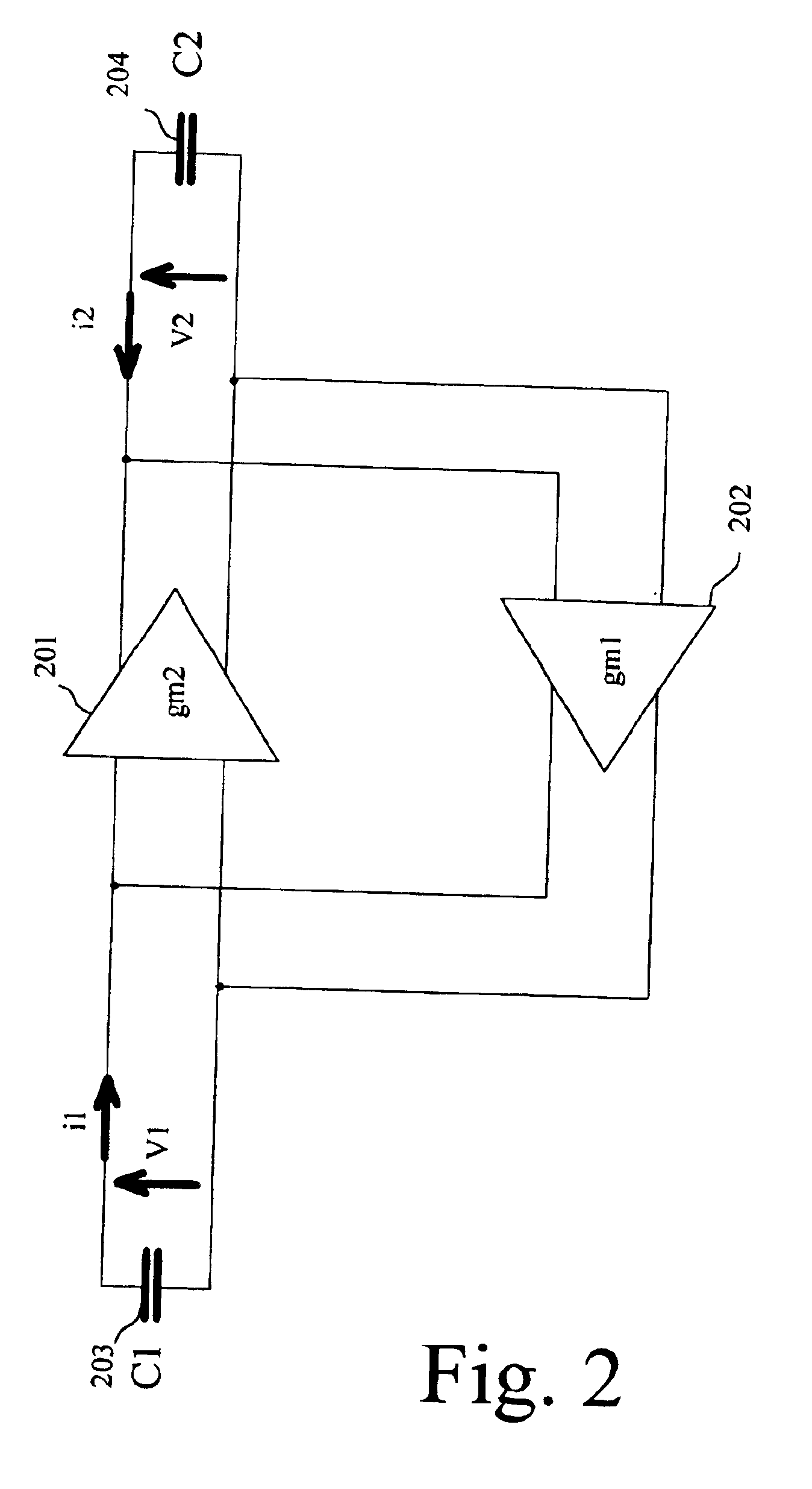
A sinusoidal frequency generator comprising an oscillation circuit controlled by a control voltage, characterized in that the oscillating circuit is a gyrator made up of two transconductance amplifiers whose bias points are fixed by the control voltage in order to regulate oscillation frequency. The gyrator is easy to integrated in a phase control loop in order to realize a square-to-sinusoidal frequency converter.

Description

This application is based upon and claims priority from prior French Patent Application No. 0210747, filed Aug. 30, 2002, the disclosure of which is hereby incorporated by reference in its entirety.1. Field of the InventionThe present invention relates to circuits generating sinusoidal frequencies, and more particularly to a converter circuit generating a sinusoidal signal.2. Description of Related ArtThe implementation of sinusoidal signal generator circuits is well known in the background art. In general, to generate a sinusoidal signal, one frequently starts from a periodic square signal, generated by a digital frequency synthesizer; this signal is then filtered through one or more band-pass filters in order to extract its fundamental harmonic. The advantage of such a process lies in the fact that the frequency of the generated sinusoidal signal can be set to the frequency of the square signal, thus benefiting from digital synthesizers' precision. On the other hand, the large amo...

Claims


Application Information

Patent Timeline
Patent Type & Authority Patents(United States)
IPC IPC(8): H03L7/089H03L7/099H03L7/08H03B5/00H03B5/24H03B28/00
CPCH03B5/24H03L7/099H03L7/0891H03B28/00
Inventor GRILLO, LIONEL
Owner STMICROELECTRONICS SRL
Learn More