
Polyphase hydraulic drive system

a hydraulic drive system and polyphase technology, applied in the direction of positive displacement engines, reciprocating piston engines, gearing, etc., can solve the problems of valve system design complexity, valve system inefficiency, maintenance, etc., and achieve the effect of simple direct coupling

Inactive Publication Date: 2005-01-04
BOREALIS TECH LTD
View PDF8 Cites 27 Cited by
  • Summary
  • Abstract
  • Description
  • Claims
  • Application Information

AI Technical Summary

Benefits of technology

A technical advantage of the present invention is that the input drive system is connected directly to the output drive system, thereby eliminating the need for valves.

Problems solved by technology

Such valve systems add extra complexity to the design of these systems, and they require associated controlling mechanisms.
In addition valve systems introduce some inefficiency into the device, and require maintenance.

Method used


Image

  • Polyphase hydraulic drive system
  • Polyphase hydraulic drive system
  • Polyphase hydraulic drive system

Examples


Embodiment Construction

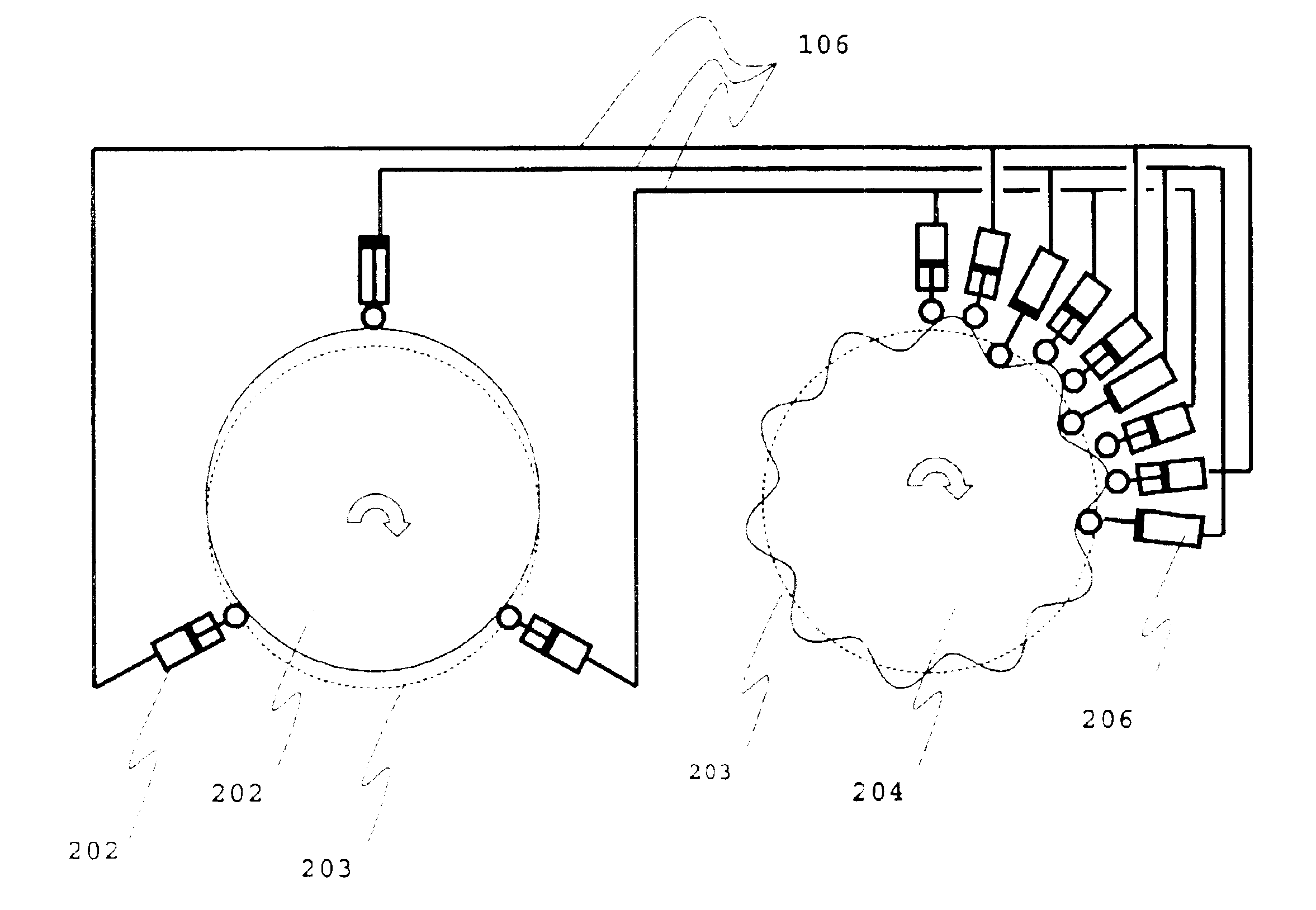
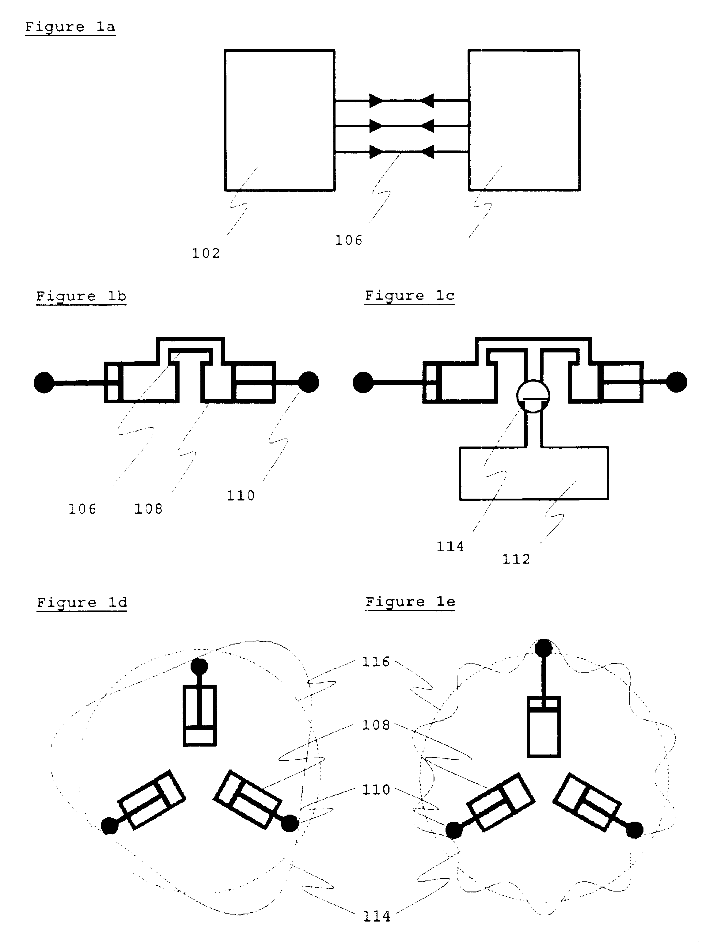
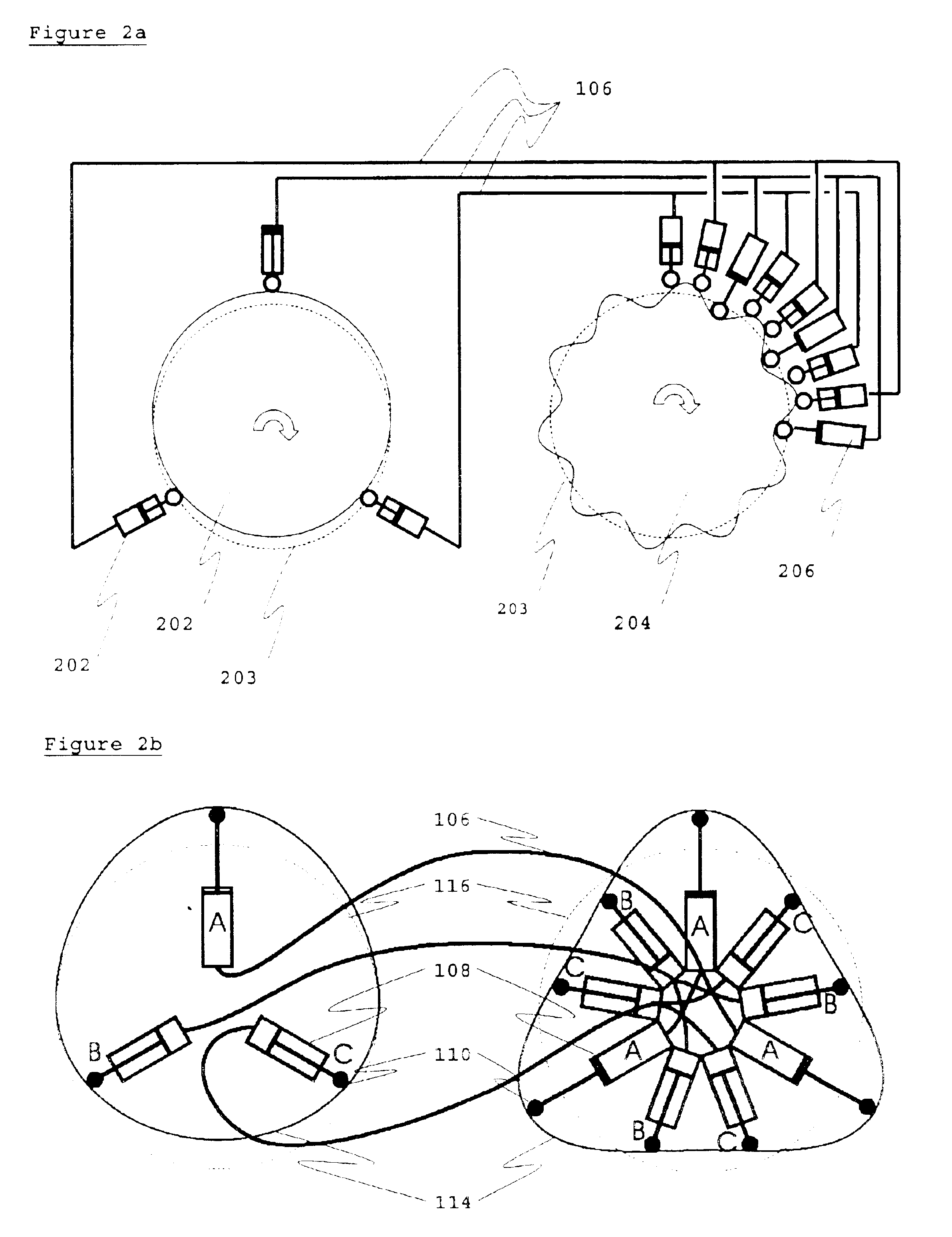
An embodiment of the present invention and its advantages are best understood by referring in more detail to FIGS. 1 through 3, in which like numerals refer to like parts throughout.

Referring now to FIG. 1a, which shows a simple schematic of the present invention, an input drive system 102 and output drive system 104 are directly connected by hydraulic lines 106. In this example, the input drive system produces three phases of oscillating fluid output, and these are fed independently and directly to the output drive system by three fluid lines. The connection between the hydraulic elements on the input drive side and the output drive side may be achieved in a number of ways known to the art. For example, the hydraulic elements may be two piston units 108 with cam-followers 110 directly connected as shown in FIG. 1b. The pistons are very simple single port pistons, with drive and driven pistons directly connected. The piston pair can be connected via a check valve 114 to a fluid rese...


PUM


Abstract

The present invention comprises an input drive system, which provides a plurality of phases of oscillating fluid flow, and an output drive system connected directly to the input drive system that is powered by the plurality of phases of oscillating fluid flow. The input drive system comprises a plurality of pistons that are caused to move in a reciprocating fashion by a power source. The power source may be a rotating power source, such as that provided by an electric motor, a diesel or petrol engine, or a turbine system. The input drive system comprises a cam ring attached to a rotating power source, a plurality of cam rollers in contact with the cam ring; and a plurality of pistons attached to the cam rings. The output drive system comprises one or more pistons that are attached to move in a reciprocating fashion by the oscillating fluid flow provided by the input drive system. The output drive system comprises a cam ring attached to a load, a plurality of cam rollers in contact with the cam ring, and a plurality of pistons attached to the cam rings.

Description

BACKGROUND OF THE INVENTIONThe present invention relates to hydraulic drive systems for gear-less inter-conversion of rotational energy and gear-less conversion of rotational energy to linear kinetic energy.Henricson (U.S. Pat. No. 5,657,681) discloses a hydraulic drive system comprising a plurality of hydraulically driven piston units with cam rollers, which are disposed to act against a wave-shaped cam profile of a cam curve element, so that linear movement of the cam rollers against the cam profile produces a relative driving movement between the cam element and the piston units. The characterizing feature of the invention is that the drive system is composed of separate, assembled cam curve element modules and separate assembled piston units.Reboredo (U.S. Pat. No. 5,689,956) discloses a hydraulic variable speed drive assembly including a hydraulic pump having a cylinder with an associated end cover, a hydraulic motor having a cylinder with an associated end cover, and an interm...

Claims


Application Information

Patent Timeline
IPC IPC(8): F01B1/00F01B1/06F01B11/00F16H39/00F16H39/18F16H39/20
CPCF01B1/06F16H39/20F16H39/18F01B11/00
Inventor EDELSON, JONATHAN SIDNEY
Owner BOREALIS TECH LTD
Learn More