
Flexible detonator system

Inactive Publication Date: 2005-01-04
DETNET SOUTH AFRICA (PTY) LTD
View PDF11 Cites 34 Cited by
  • Summary
  • Abstract
  • Description
  • Claims
  • Application Information

AI Technical Summary

Benefits of technology

An object of the present invention is to provide an electronic detonator system which exhibits flexibility, safety and reliability, which results in the restrictions and problems of prior-art technique being essentially obviated. This object aims at providing an electronic detonator system, the “intelligence” of which is found in a reusable control unit, while its detonators preferably have a simple and inexpensive design.
Another object of the invention is to provide a method for controlling a plurality of electronic detonators included in an electronic detonator system, the method being especially suitable for controlling electronic detonators having a simple design.
The detonators connected to the control unit are preferably formed completely without the components mentioned above. According to one aspect of the invention, a detonator is provided with electronic circuitry which is adapted to respond to signals (digital data packets etc.) from the control unit. On the other hand, the detonator does not need to contain any microprocessor or software. It has turned out to be very advantageous that the detonator lacks such parts since a detonator which is too autonomous and has complicated functions may lead to unfortunate malfunction. A detonator having a complex construction also contributes to a higher price of the detonator.
The state parameters of the status register preferably indicate either of two possible values, whereby these state parameters indicate whether a certain condition is present in the detonator. Due to the “binary”, or divalent, character of the state parameters, these are often called “flags”. A difference in comparison with prior-art technique is thus that these flags are readable from the control unit, instead of just being used by internal electronics in the detonators. This difference is in line with the basic knowledge that the “intelligence” of the system may be located in the control unit, whereby the internal electronics in the detonators can be allowed to be very simple.
From another aspect of the invention, an electronic detonator is provided, in which calibration of the internal clock of the detonator is performed in relation to the accurate, external clock oscillator in the control unit. Calibration of the delay time may be in progress at the same time as regular signalling and other activities are going on in the system. Since the detonators essentially have a relatively simple construction, this calibration is performed by simple counting of external and internal clock pulses from the external and the internal clock oscillators, respectively. The signalling format of the system is formed in such a manner that external calibration pulses may be extracted from the regular signalling of the control unit. Due to the fact that external calibration pulses are extracted from the regular signalling, communication between the control unit and the detonators, and other activities, may begin progress in parallel with the calibration. Thus, the time until the detonators are ready to be fired is minimised.
In order to provide high-definition and exact delay times, calibration is performed in a preferred embodiment during several seconds. Transfer of delay times to detonators that are connected to the control unit may thus take place in parallel with the calibration. This may be a great advantage, for instance, when a very large number of detonators are connected (the system may, for example, allow up to 1000 detonators on the same bus).

Problems solved by technology

However, prior-art electronic detonators and electronic detonator systems suffer from certain restrictions and problems.
A problem of prior-art electronic detonator systems is that it has often been necessary to weigh up, on the one hand, the functionality of the system in terms of control capabilities and, on the other hand, the cost of a detonator included in the system.
Prior-art electronic detonator systems also have a restriction as regards the preparation of the detonators which has been time-consuming, which means that in practice the number of detonators which could be connected to one and the same system has been limited.
The number of detonators in one and the same system has also been limited due to the fact that too high signal levels have been required for communication in a system with many detonators.
The more detonators included in the system, the more difficult to communicate with the “last” detonator.

Method used


Image

  • Flexible detonator system
  • Flexible detonator system
  • Flexible detonator system

Examples


Embodiment Construction

In the following some preferred embodiments of the invention will be described in more detail.

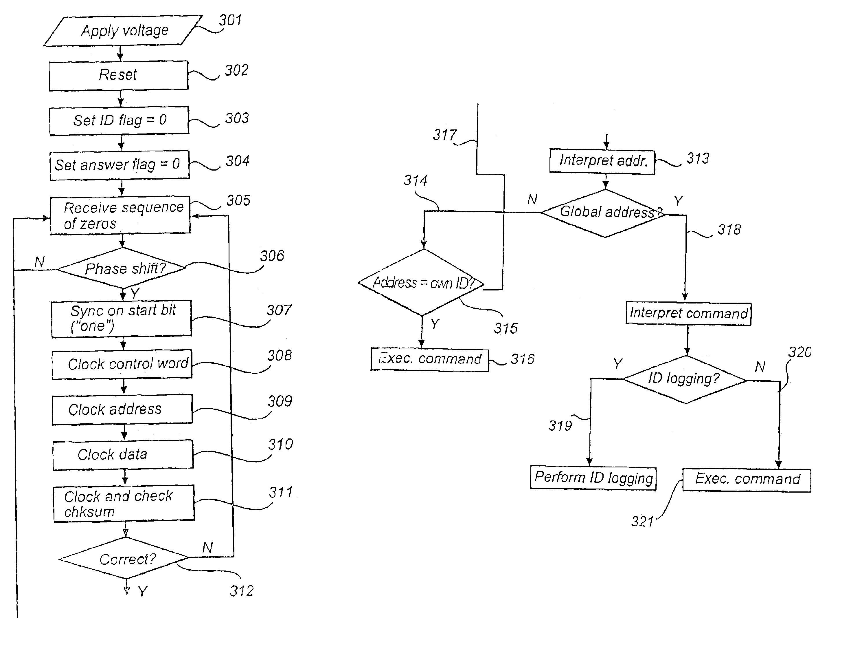
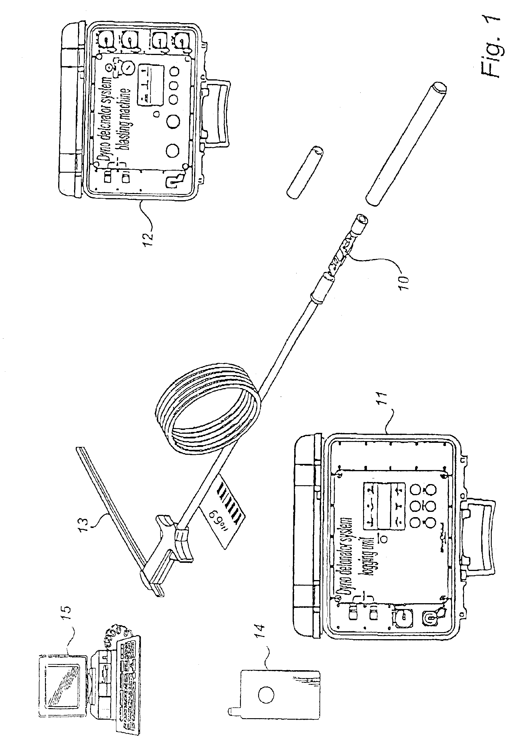
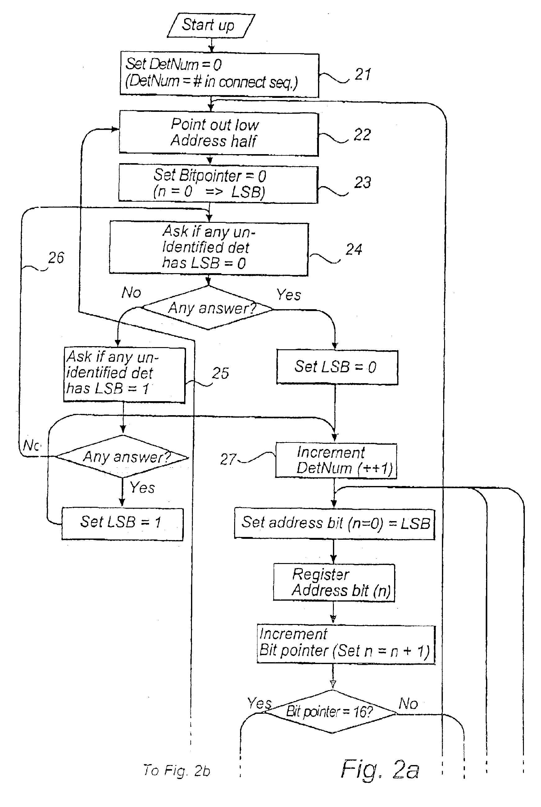
FIG. 1 shows a number of system units which are included in an electronic detonator system. A preferred embodiment of an electronic detonator system according to the invention comprises a plurality of electronic detonators 10 which are connected to a control unit 11, 12 via a bus 13. The purpose of the bus is to convey signals between the control unit 11, 12 and the detonators 10, i.e. to allow communication between them, and to supply power to the detonators. The control unit may comprise either a logging unit 11 (for example when electronic detonators are connected to the bus) or a blasting machine 12 (for instance when connected detonators are being prepared for firing and in connection with firing). Besides, the detonator system according to the invention comprises a portable message receiver 14 which is adapted to be carried by the person connecting the detonators to the bus. Via the p...


PUM


Abstract

An electronic detonator system includes a control unit, a plurality of electronic detonators and a bus which connects the detonators to the control unit. Each electronic detonator includes a number of flags which may assume either of two possible values, each flag indicating a substate of the respective detonators. The flags are readable from the control unit by means of digital data packets and the control unit is adapted, by means of these flags, to check the state of the electronic detonator and control the operation of the electronic detonator. When reading the flags, the electronic detonators give responses in the form of analog response pulses on the bus. The detonator system also includes a portable message receiver which on the basis of the flags obtains messages regarding the connecting status of a detonator.

Description

TECHNICAL FIELDThe present invention generally relates to the firing of explosive charges. More particularly, the invention relates to a flexible, electronic detonator system and associated electronic detonators. The invention also relates to a method for controlling said system.BACKGROUND ARTDetonators in which delay times, activating signals etc. are controlled electronically, are generally placed in the category electronic detonators. Electronic detonators have several significant advantages over conventional, pyrotechnic detonators. The advantages include, above all, the possibility of changing, or “reprogramming”, the delay time of the detonator and allowing shorter and more exact delay times than in conventional, pyrotechnic detonators. Some systems with electronic detonators also allow signalling between the detonators and a control unit.However, prior-art electronic detonators and electronic detonator systems suffer from certain restrictions and problems.A detonator system h...

Claims


Application Information

Patent Timeline
IPC IPC(8): F42D1/00F42D1/05F42C19/08
CPCF42C11/06F42D3/04F42D1/055F42D1/05
Inventor HALLIN, SUNEBOKVIST, ANNE-MARIEWESTBERG, JANJONSSON, ELOF
Owner DETNET SOUTH AFRICA (PTY) LTD
Learn More