Valve actuating apparatus for internal combustion engine

a technology of valve actuation and internal combustion engine, which is applied in the direction of machines/engines, output power, electric control, etc., can solve the problems that the pumping loss during cruising or in the low-load operating region of the engine cannot be sufficiently reduced, and the combustion rate is reduced, so as to achieve stable combustion and improve fuel economy

Inactive Publication Date: 2005-01-04
HONDA MOTOR CO LTD
View PDF4 Cites 22 Cited by
  • Summary
  • Abstract
  • Description
  • Claims
  • Application Information

AI Technical Summary

Benefits of technology

It is an object of the invention to provide a valve actuating apparatus for an internal combustion engine, which is capable of achieving stable combustion and improved fuel economy at the same time during cruising or in a low-load operating region of the engine, when the engine selectively operates either in the normal Otto cycle and in the Miller cycle.
Further, the first to fourth rocker arms are arranged in order of the fourth, first, second and third rocker arms. The first rocker arm is smaller in width than the third rocker arm, and hence when the rocker arms are arranged as above, the distance, as viewed along the axis of the camshaft, between the center of the combustion chamber and the end of the fourth rocker arm can be made shorter than in the case where the fourth rocker arm is disposed at a location axially outward of the third rocker arm, which makes it possible to arrange all the rocker arms in a manner well-balanced with respect to the combustion chamber.

Problems solved by technology

However, the above conventional valve actuating apparatus suffers from the following problems: When the engine is in the low-load operating region, fuel economy can be improved during cruising of the vehicle, as described above, but during the starting and idling of the engine, opening and closing of the intake valve by the delayed-closing cam causes degradation of combustion in the cylinder, resulting in unstable combustion.
Further, when a delayed-closing cam modified in cam profile for reduced delay in valve-closing timing is used so as to prevent degradation of combustion, pumping loss during cruising or in the low-load operating region of the engine cannot be sufficiently reduced, which reduce the above-mentioned effect of the improvement of fuel economy.
In short, during cruising of the vehicle, or in the low-load operating region of the engine, it is difficult to achieve both of stable combustion and improved fuel economy at the same time.

Method used


Image

  • Valve actuating apparatus for internal combustion engine
  • Valve actuating apparatus for internal combustion engine
  • Valve actuating apparatus for internal combustion engine

Examples


Embodiment Construction

Hereafter, the invention will be described in detail with reference to the drawings showing preferred embodiments thereof.

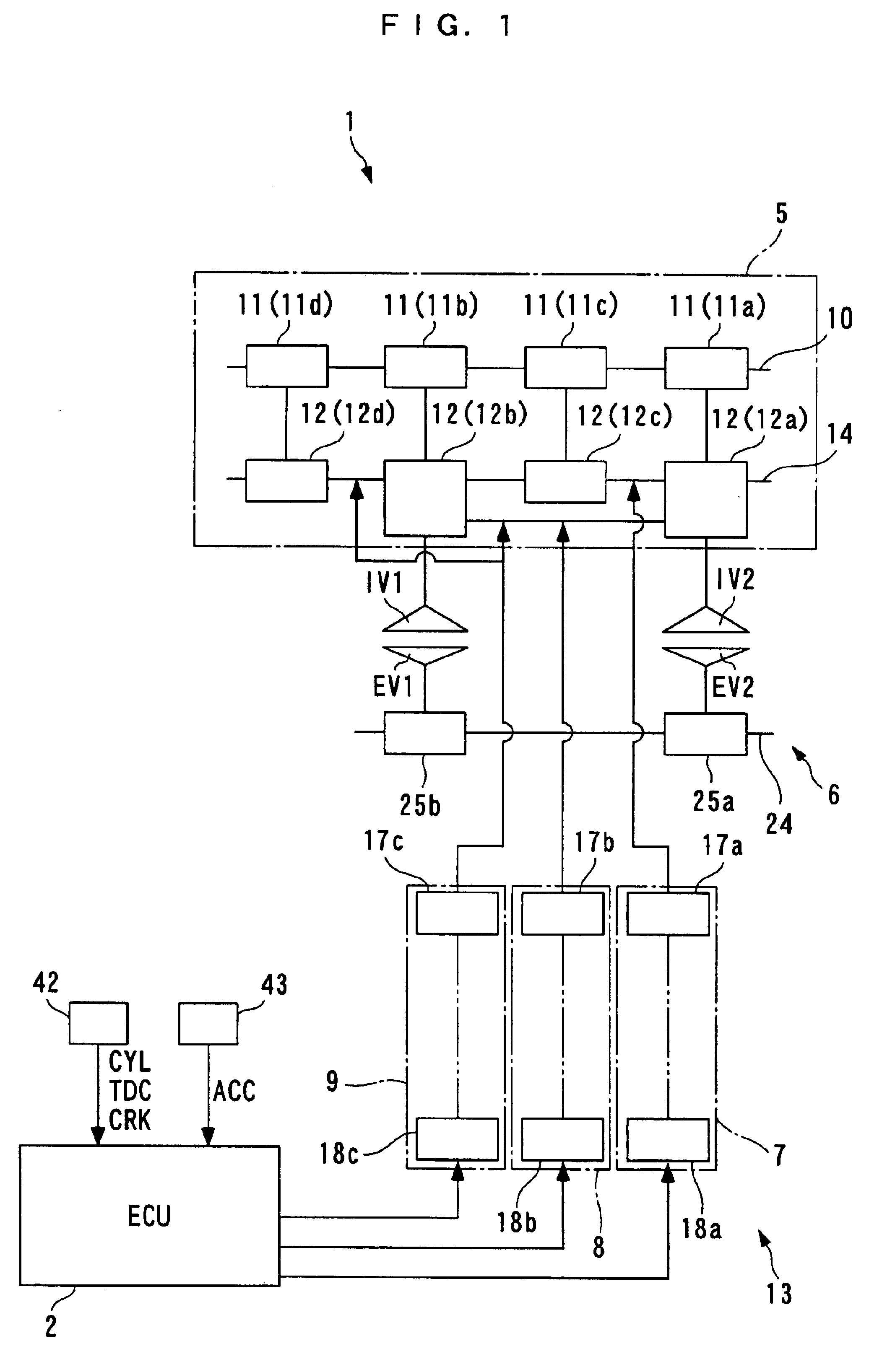
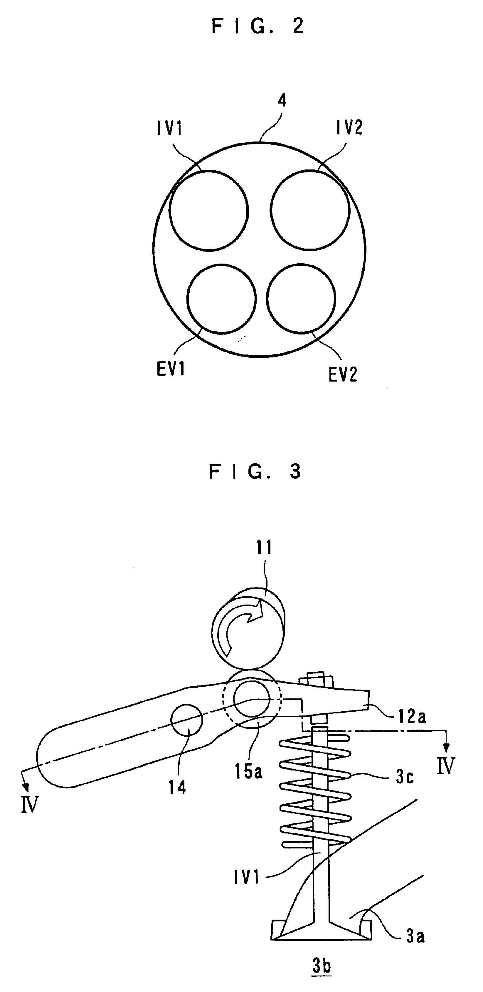
Referring first to FIG. 1, there is schematically shown the arrangement of a valve actuating apparatus 1 for an internal combustion engine, according to a first embodiment of the invention. The internal combustion engine (hereinafter simply referred to as “the engine”) 3 is an inline four-cylinder (only one of the cylinders is shown in FIG. 2) DOHC gasoline engine installed on a vehicle, not shown. As shown in FIG. 2, each cylinder 4 is provided with first and second intake valves IV1, IV2 (intake valve) and first and second exhaust valves EV1, EV2. As illustrated in FIG. 3 showing the first intake valve IV1 by way of example, the intake valves IV1, IV2 are arranged such that each of them is movable between a closed position (shown in FIG. 3) for closing an intake port 3a of the engine 3 and an open position (not shown) projected into a combustion changer 3b, for...


PUM


Abstract

A valve actuating apparatus for an internal combustion engine selectively operating in the normal Otto cycle or the Miller cycle is provided which enables the engine to achieve stable combustion and improved fuel economy during cruising or in a low-load engine operating region. A delayed-closing cam for Miller cycle operation and a normal cam having a cam profile for earlier valve-closing timing of the intake valve than a cam profile of the delayed-closing cam are provided on a camshaft. A cam profile-switching mechanism switches between the delayed-closing cam and the normal cam, for opening and closing the intake valve. An ECU controls the switching mechanism such that when a detected operating condition of the engine indicates starting or idling, the intake valve is operated by the normal cam, and when the detected operating condition indicates cruising, the intake valve is operated by the delayed-closing cam.

Description

BACKGROUND OF THE INVENTION1. Field of the InventionThis invention relates to a valve actuating apparatus for an internal combustion engine, which controls opening / closing operations of an intake valve, particularly valve-closing timing of the same.2. Description of the Prior ArtConventionally, a valve actuating apparatus of the above-mentioned kind is disclosed e.g. in Japanese Utility Model Publication (Kokoku) No. 56-9045. This valve actuating apparatus comprises a camshaft that rotates in synchronism with rotation of a crankshaft of an internal combustion engine, a pair of cams having different cam profiles, a pivotally movable rocker arm that comes into contact with a selected one of the two cams and is held in contact with an intake valve, a rocker shaft that pivotally movably supports the rocker arm, and a switching mechanism that switches a cam for contact with the rocker arm, between the pair of cams.The pair of cams are comprised of a normal cam and a delayed-closing cam. ...

Claims


Application Information

Patent Timeline
Patent Type & Authority Patents(United States)
IPC IPC(8): F01L1/26F02D13/02F01L13/00F02D15/00F02D41/04F02D41/06F02D41/08
CPCF01L1/022F01L1/267F01L13/0036F02D13/0207F02D13/0234F02D13/0257F02D13/0269F01L2800/00Y02T10/142F02D13/0203Y02T10/12
Inventor MATSUURA, KATSUYATAKAHASHI, HITOSHITAKAYAMA, MASAKISUGIMOTO, MITSURUMORITA, TERUYOSHIKIMURA, TOMIO
Owner HONDA MOTOR CO LTD
Why Eureka
Try Eureka