Ventilation system for a protective suit

a ventilation system and protective suit technology, applied in the direction of respirators, life-saving devices, inhalators, etc., can solve the problems of general discomfort of workers using protective suits, temperature and humidity may rise rapidly, and the effect of reducing the number of people in the protective sui

Inactive Publication Date: 2005-01-04
SAFETY EQUIP SWEDEN AB C 2 SAFETY EQUIP AUSTRALIA
View PDF39 Cites 76 Cited by
  • Summary
  • Abstract
  • Description
  • Claims
  • Application Information

AI Technical Summary

Benefits of technology

Valves may be fitted to the suit to allow free egress of air from the suit, but preventing inward flow in cases where the ventilation system fails. The air outlet from the suit or mask may be filtered to ensure it does not pollute, for instance, a clean room. The ventilating hose (or hoses) is also fitted with non-return valves to prevent air flowing back to the respirator when the supply pressure falls below ambient, for example, during power off operation.
An inlet valve may be provided to control the inlet of air to the pump and filter unit. The inlet valve may be arranged upstream or downstream of the fan to close when a defined air pressure is present within the pump unit. With this valve it is easier to ensure that there is always a positive pressure within the face piece at all times, and so to avoid a negative pressure which could give rise to the entry of the contaminated air.

Problems solved by technology

One big disadvantage for workers using protective suits is that they are generally uncomfortable.
Consequently, the temperature and humidity may rise rapidly during work.
In extreme circumstances humidity approaches 100%, the body's natural cooling system stops working as no water can evaporate from the skin, blood temperature increases and, if work continues, heat stress results.
These devices reduce the inhalation resistance created by the filters, and increase the level of protection by creating positive pressure in the face piece.
Constant speed respirators (PAPRs) deliver substantially constant flow rates at all times. During exhalation the air flow is wasted, and during heavy inhalation the demand often exceeds the delivery rate, resulting in negative pressure in the breathing mask and increased breathing resistance.

Method used


Image

  • Ventilation system for a protective suit
  • Ventilation system for a protective suit
  • Ventilation system for a protective suit

Examples


Embodiment Construction

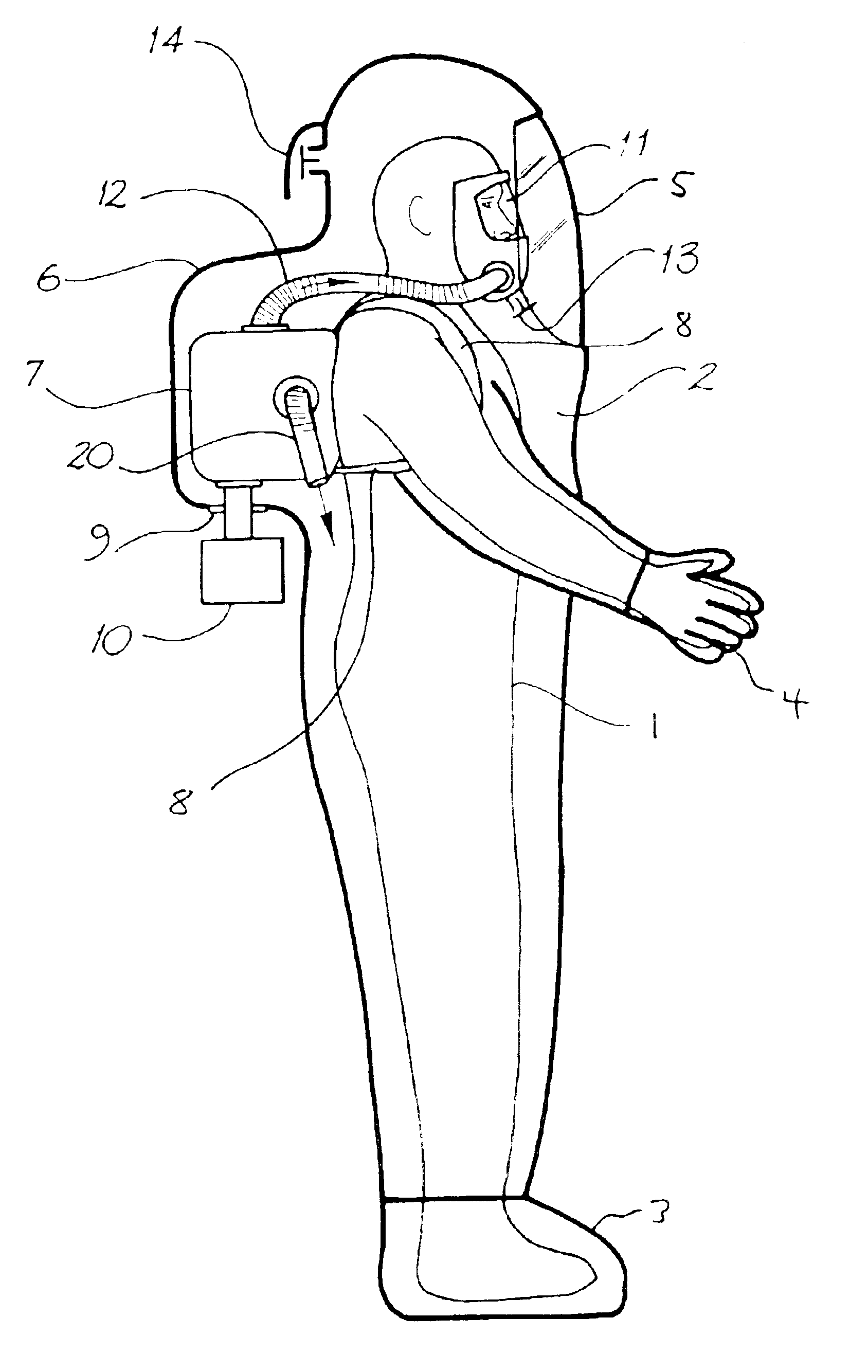
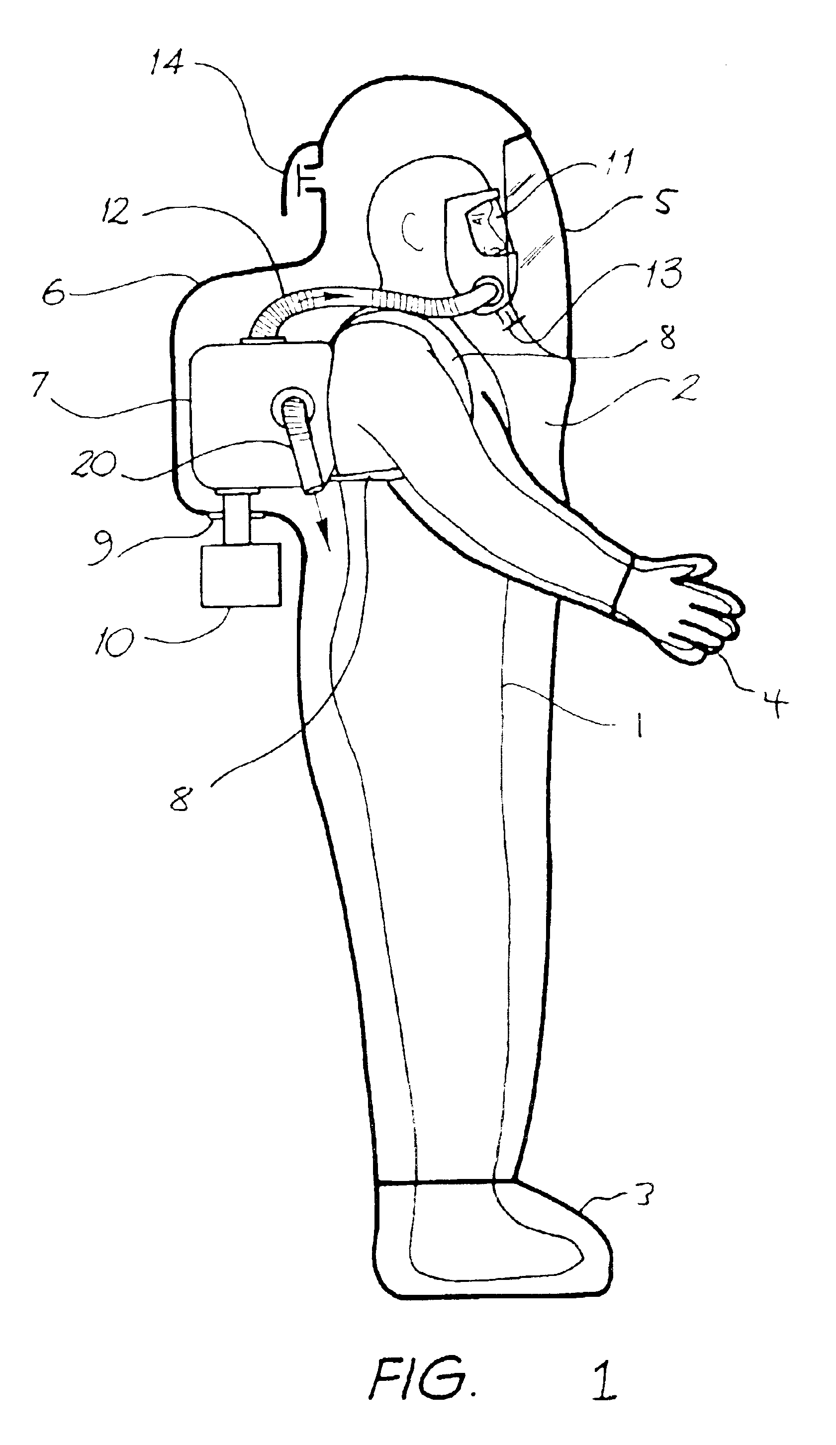
Referring to FIG. 1, user 1 is wearing a gas-tight polyamide protective suit 2. Boots 3 are sealed to the suit around the ankles, and gloves 4 are sealed around the wrists to provide complete protection from the environment. A transparent panel of chemical resistant PVC 5 allows the user to view the environment. An extension 6 of the suit covers an APR unit 7.

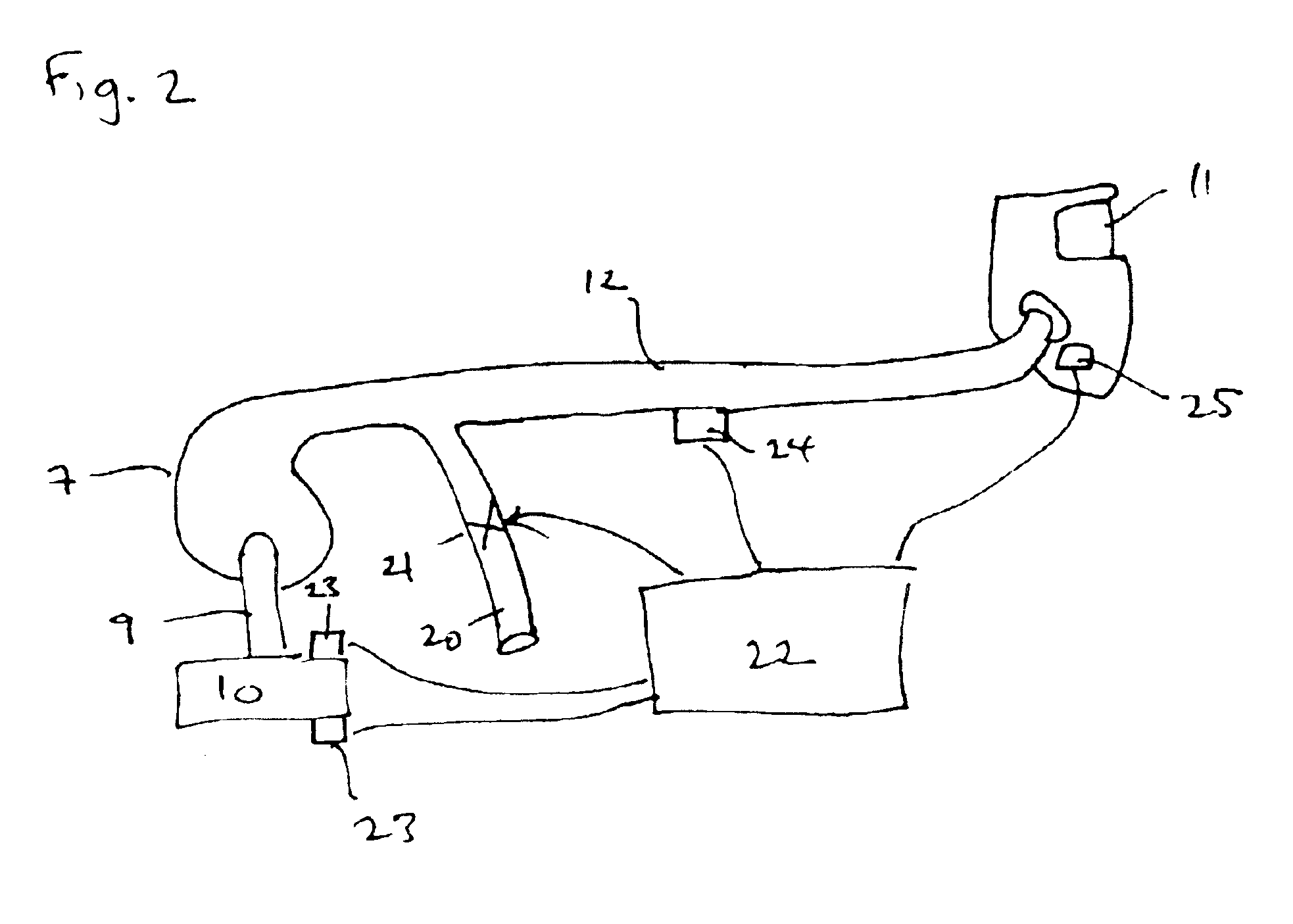
Inside the suit 2, the user wears a harness 8 to mount the APR unit 7 on his back. A hole 9 in the back of the suit provides an air inlet port for the APR unit to take atmospheric air from the environment. A filter 10 connects to the APR unit and seals hole 8 to prevent ingress of atmospheric gases into the suit. To do this the filter will screw onto a spigot extending from the APR unit and clamp a rubber seal around the hole between the filter and APR.

The APR unit 7 pumps filtered air to face piece 11 via hose 12. The air in the face piece 11 is at a higher pressure than the air within the rest of the suit, however it does not...


PUM


Abstract

The present invention relates to a ventilation system for a protective suit for use in hazardous environments. In a further aspect it concerns the protective suit itself. An air purifying respirator draws air from outside the protective suit through a filter, supplies filtered breathing air via a breathing hose to a space within the face piece, and supplies filtered ventilating air via a ventilating hose to the interior of the protective suit. A ventilation valve in the ventilating hose automatically closes only during periods of high breathing demand to counter a pressure drop inside the face piece.

Description

FIELD OF THE INVENTIONThe present invention relates to a ventilation system for a protective suit for use in hazardous environments. In a further aspect it concerns the protective suit itself.BACKGROUND OF THE INVENTIONProtective suits are available for a range of hazardous environments, including hazardous chemicals in liquid and vapor form. One big disadvantage for workers using protective suits is that they are generally uncomfortable. To achieve good protection, the suit must be sealed to the wearer's body and therefore offers a significant barrier to heat transfer by convection, conduction, radiation and evaporation. Consequently, the temperature and humidity may rise rapidly during work. In extreme circumstances humidity approaches 100%, the body's natural cooling system stops working as no water can evaporate from the skin, blood temperature increases and, if work continues, heat stress results.Air purifying respirators (APRs) are mounted to the suit to provide filtered air t...

Claims


Application Information

Patent Timeline
Patent Type & Authority Patents(United States)
IPC IPC(8): A62B17/00
CPCA62B17/005A62B17/006
Inventor BEIZNDTSSON, GORAN B. C.BACKMAN, LENNART
Owner SAFETY EQUIP SWEDEN AB C 2 SAFETY EQUIP AUSTRALIA
Why Eureka
Try Eureka