Piston and rod assembly for air-actuated variable damping

a variable damping and piston adapter technology, applied in the field of valved dampers, can solve the problems of easy identification of inconvenient assembly, inability of piston adapters to crimp to the valve support, and the detection of faulty products, so as to achieve easy and reliably manufacture and assembly.

Inactive Publication Date: 2005-01-04
BWI CO LTD SA +1
View PDF17 Cites 16 Cited by
  • Summary
  • Abstract
  • Description
  • Claims
  • Application Information

AI Technical Summary

Benefits of technology

This invention solves the above-described and other problems associated with known systems by providing a damper with variable damping fluid flow control in a preferred monotube design. This is accomplished through variable state pressure regulation in a valved damper piston. A damper according to presently preferred embodiments of this invention is more easily and reliably manufactured and assembled into a robust damper for implementation in a commercial production environment.
In presently preferred embodiments of this invention, a piston assembly includes unique and advantageous alternatives for connecting the piston to the output rod, piston seal plate and spring retainer configurations, and joinder mechanisms for the piston to the valve support. Each aspect of this invention offers significant manufacturing and reliability advantages and can be implemented individually or in various combinations.
Several alternatives are available according to this invention to connect the output rod to the piston adapter. This connection must both (1) be able to withstand fluid and mechanical forces and (2) seal the fluid outside of the piston from the gas inside the piston. A first embodiment is particularly useful where the output rod has a sufficient diameter for a shoulder to be included thereon. A tapered seat between the output rod and the piston adapter aligns the two pieces, seals between them, and provides a surface to oppose the tension of a threaded connection between the two components. Another embodiment involves resistance-welding the output rod to the piston adapter. This also provides a leak-tight, strong joint. Another alternative includes a snap ring to accomplish the alignment and strength functions, while a thread sealant provides the sealing function.

Problems solved by technology

If the plate is installed upside down, the incorrect assembly is easily identified.
If not visually identified by the assembler, however, the piston adapter would not be able to crimp to the valve support, ensuring that the faulty product will be noticed.

Method used


Image

  • Piston and rod assembly for air-actuated variable damping
  • Piston and rod assembly for air-actuated variable damping
  • Piston and rod assembly for air-actuated variable damping

Examples


Embodiment Construction

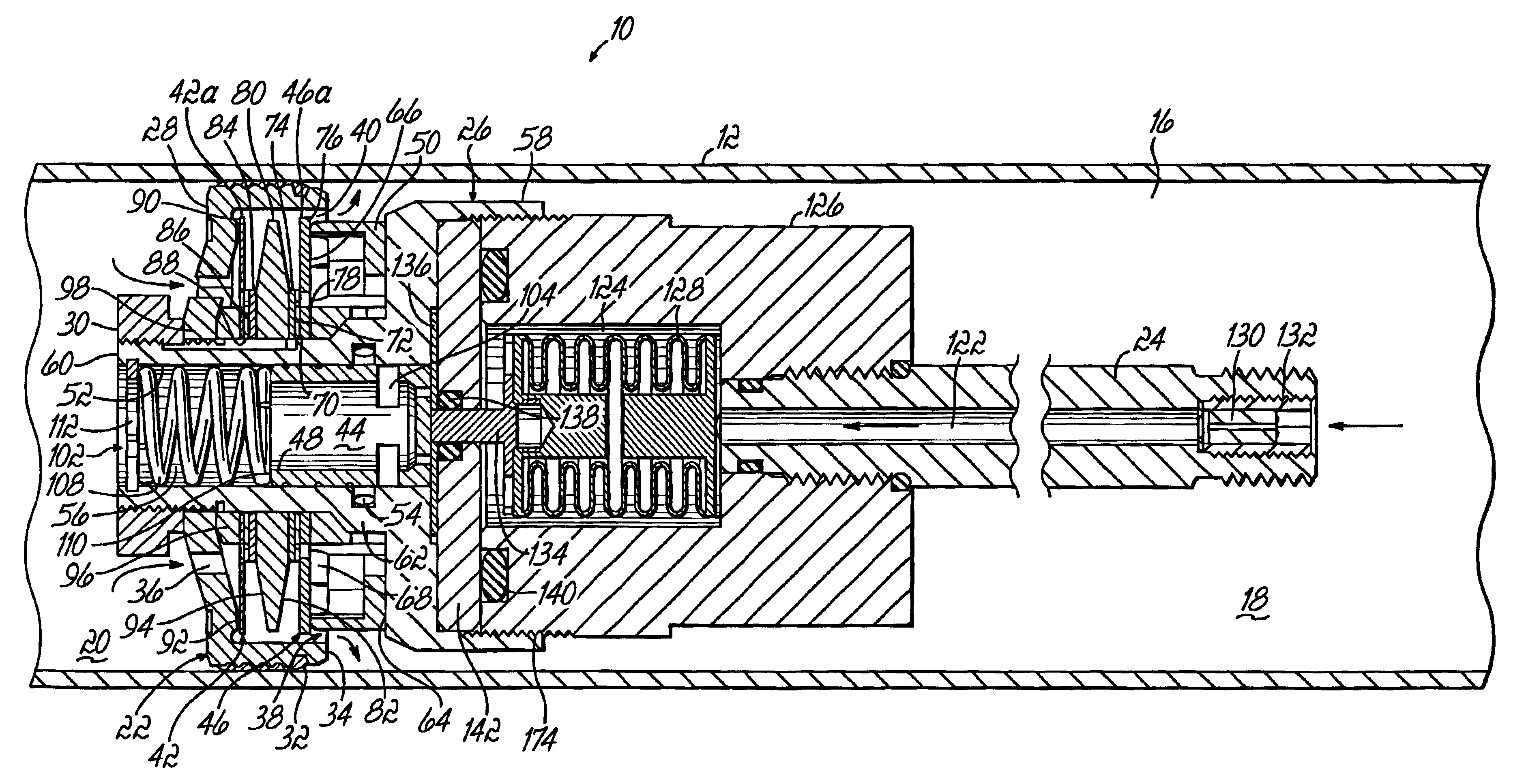
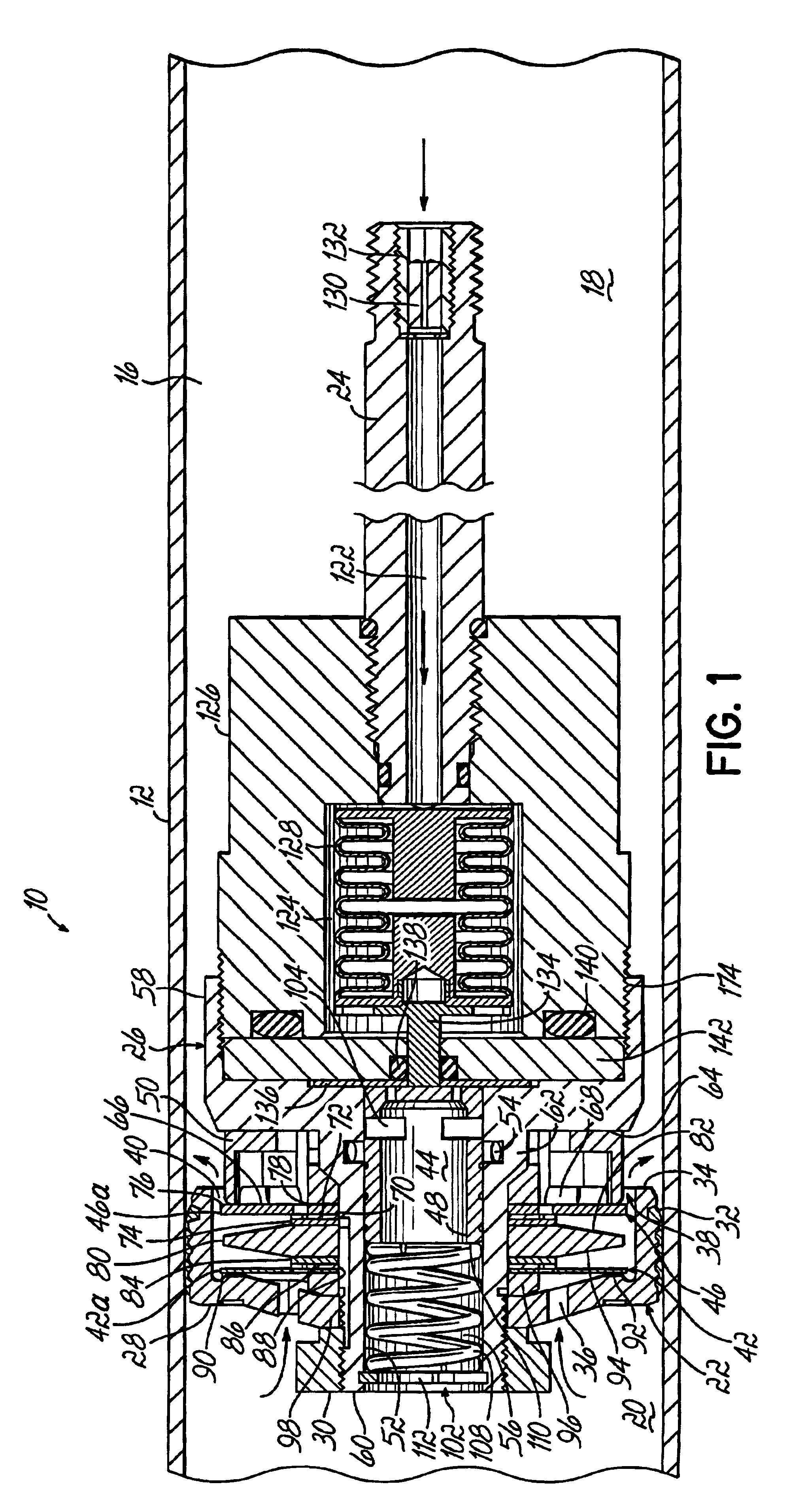
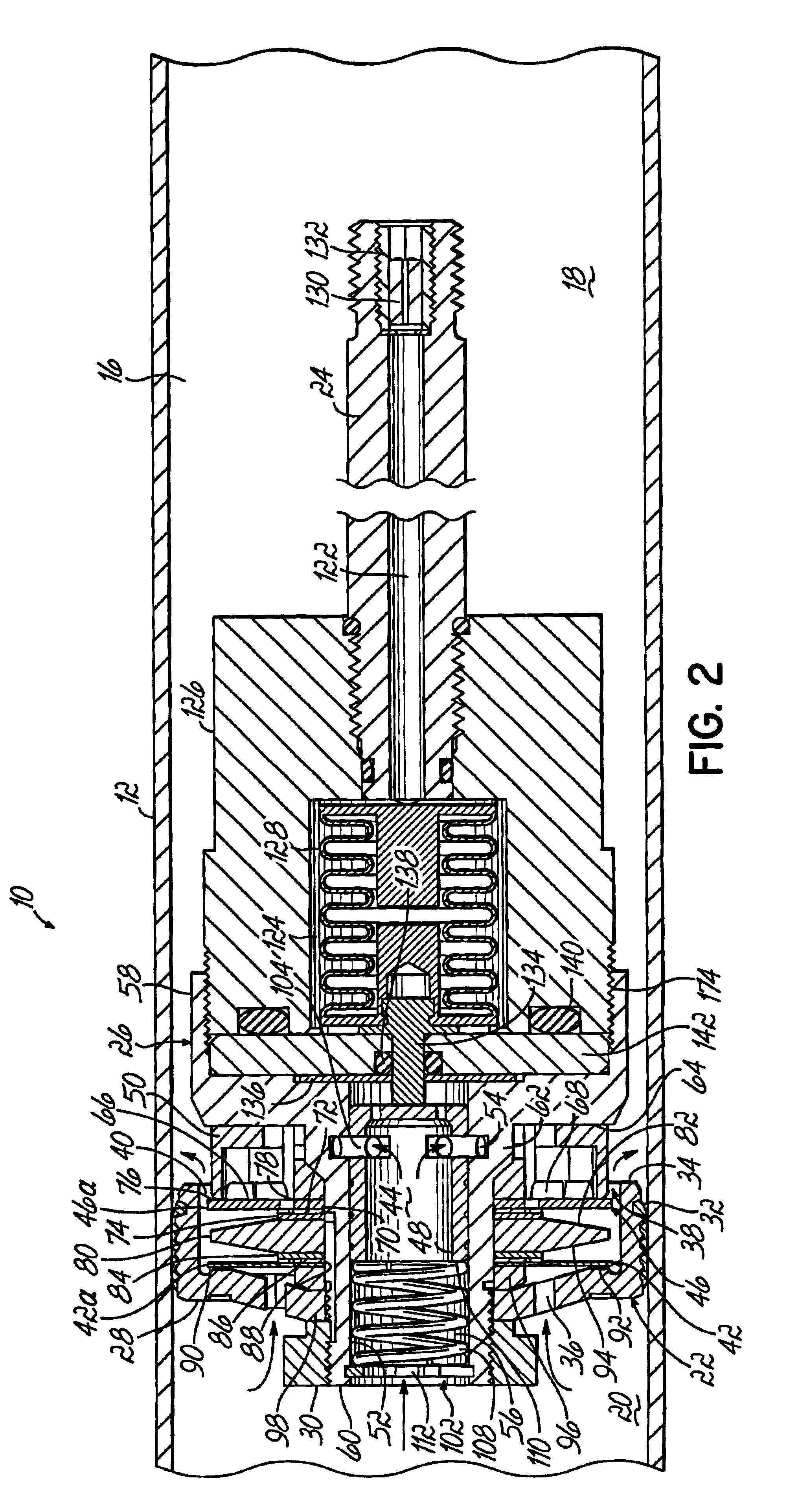
Referring to the drawings, illustrated in FIGS. 1 and 2 is an alternating state pressure regulation valved monotube suspension damper embodied as a shock absorber 10 according to a presently preferred embodiment of this invention. The vehicle suspension damper or shock absorber 10 includes a single tube designated as cylinder 12. Cylinder 12 has a closed lower end (not illustrated), and an upper end closed by a rod guide (not illustrated), in a conventional manner defining cylindrical cavity 16. Cavity 16 is divided into an extension chamber 18 and a compression chamber 20 by a piston assembly 22. Piston assembly 22 is sealingly disposed in cylinder 12 for slidable axial movement therein.

Securely connected to piston assembly 22 is piston rod 24 which extends through the extension chamber 18 of the cylinder tube 12 exiting the cavity 16 through the rod guide. The upper end of the piston rod 24 is adapted for connection to the sprung mass (body), of the motor vehicle (not illustrated)...


PUM


Abstract

A damper includes a piston that carries a relatively compact control valve for controlling fluid flow through the piston. The control valve provides a variable amount of damping by regulating damper fluid flow between the extension chamber and the compression chamber of the damper during extension and compression strokes. Pressure regulation across the piston is controlled through a flow path as determined by the control valve. The damping force of the damper varies depending upon the loading conditions of the vehicle. The control valve is air pressure actuated to adjust the damping force and control the flow of fluid in the flow path. The piston and rod assembly include unique features such as a seal plate design, and spring retainer that aid in the efficient and reliable assembly in a commercial production setting.

Description

BACKGROUND OF THE INVENTIONThis invention relates generally to a valved damper and more particularly, to a damper that is pneumatically controlled to provide variable damping forces.Conventional vehicle suspension dampers typically consist of direct double-acting telescopic hydraulic passive dampers. They are generally described as either shock absorbers or struts. A primary purpose of shock absorbers is to dampen oscillations of the vehicle suspension spring. This is accomplished by converting kinetic energy in the form of motion between sprung and unsprung masses of a vehicle into heat and then dissipating the heat. Struts also serve this capacity and in addition, support reaction and side-load forces on the suspension.Typical dampers are hydraulic devices using oil as the fluid medium for converting motion into heat. As the damper is cycled, a piston is forced to move in extension and compression directions through the oil that is contained within a cylinder tube. This creates pr...

Claims


Application Information

Patent Timeline
Patent Type & Authority Patents(United States)
IPC IPC(8): B60G17/015B60G17/08B60G17/06F16F9/516F16F9/46F16F9/512F16F9/34F16F9/348F16F9/44F16F9/50F16F9/32
CPCB60G17/0152F16F9/3228F16F9/3482F16F9/461F16F9/466F16F9/512F16F9/516B60G17/08F16F2230/183B60G2206/41B60G2400/60B60G2400/61B60G2400/821B60G2500/112B60G2600/184
Inventor MILLER, TROY A.OLIVER, MICHAEL L.KRUCKEMEYER, WILLIAM C.
Owner BWI CO LTD SA
Why Eureka
Try Eureka