Foam pad and process for production thereof

a foam pad and foam technology, applied in the field of foam pads, can solve the problems of difficult use reliably, significant capital cost required to acquire hog-ring guns, and associated labor costs, and achieve the effect of reducing inventory investment and facilitating recyclability of final products

Inactive Publication Date: 2005-01-04
PROPRIETECT LP
View PDF16 Cites 32 Cited by
  • Summary
  • Abstract
  • Description
  • Claims
  • Application Information

AI Technical Summary

Benefits of technology

The present inventors have developed a novel technique for attaching a trim cover to a foam. The technique has a combination of some or all of the following advantages:can be used to produce foam pads having relatively narrow trenches (less than about 15 mm),provides for self-alignment of trim cover during attachment to the foam pad,utilizes a male-female trim cover attachment system which can be made of a polymer to facilitate recyclability of the final product,allows for implementation of relatively inexpensive mechanical fasteners (thereby obviating the use of relative expense approaches such as hook and loop (e.g., Velcro™) fasteners),simpler mode of attaching the trim cover to the foam pad thereby improving efficiency of commercial operations,can be used to provide foam pads having enhanced craftsmanship,can be implemented relatively easily thereby mitigate the requirement for highly trained personnel,allows for reduction in the need for secondary machine tooling thereby reducing the capital cost in equipment needed to carry out the process (cf. hook and loop fasteners which typically require the need for specialized tooling to accommodate magnets needed to secure fasteners in place),allows for the use of a universal mechanical attachment system thereby reducing inventory investment,allows for the use of convex and concave trench design,provides a relatively simplified manner by which foam intrusion in the mechanical attachment system may be obviated or mitigated,does not require the use of expensive and / or dangerous equipment to attach the trim cover (or other element) thereto,can be used to attach a trim cover (or other element) to a foam device around a curved portion,can be easily used to provide straight-line attachment of the trim cover (or other element) to the foam device,can provide some play or give during initial and final attachment of the trim cover (or other element) to the foam device,can be used to secure a trim cover (element) to a foam device without adversely affecting other elements of the foam device (e.g., heating elements, occupant detection systems and the like),can be used facilitate original assembly and subsequent disassembly of the foam device for maintenance or any other purpose, anddoes not render the final foam product difficult to demold.

Problems solved by technology

This approach suffers from a number of drawbacks.
For example, a significant capital cost is required to acquire the hog-ring gun and a significant associated labor cost is required to ensure that trim covers can be attached to foam devices at a rate commensurate with the rate at which the foam device is being produced.
Further, since deployment of the first hog-ring immovably secures the trim cover to foam device, there is no play or give.
Still further, this approach is difficult to use reliably when producing a vehicular seat product which incorporates one or more of a seat heater and an occupant detection system.
Still further, the use of metal in the foam device creates additional cost in recycling the finished product after complete of its life cycle.
Unfortunately, the resulting foam pad or device contains a trench typically having a width of 20 mm or more.
While this approach is reliable, it does suffer from a number of drawbacks.
For example, this type of fastener is generally regarded one of the most expensive approaches to utilize to secure a trim cover to a foam device.
Further, this approach is not well suited to fastening around a curve portion of the foam device without incurring significant wastage.

Method used


Image

  • Foam pad and process for production thereof
  • Foam pad and process for production thereof
  • Foam pad and process for production thereof

Examples


Embodiment Construction

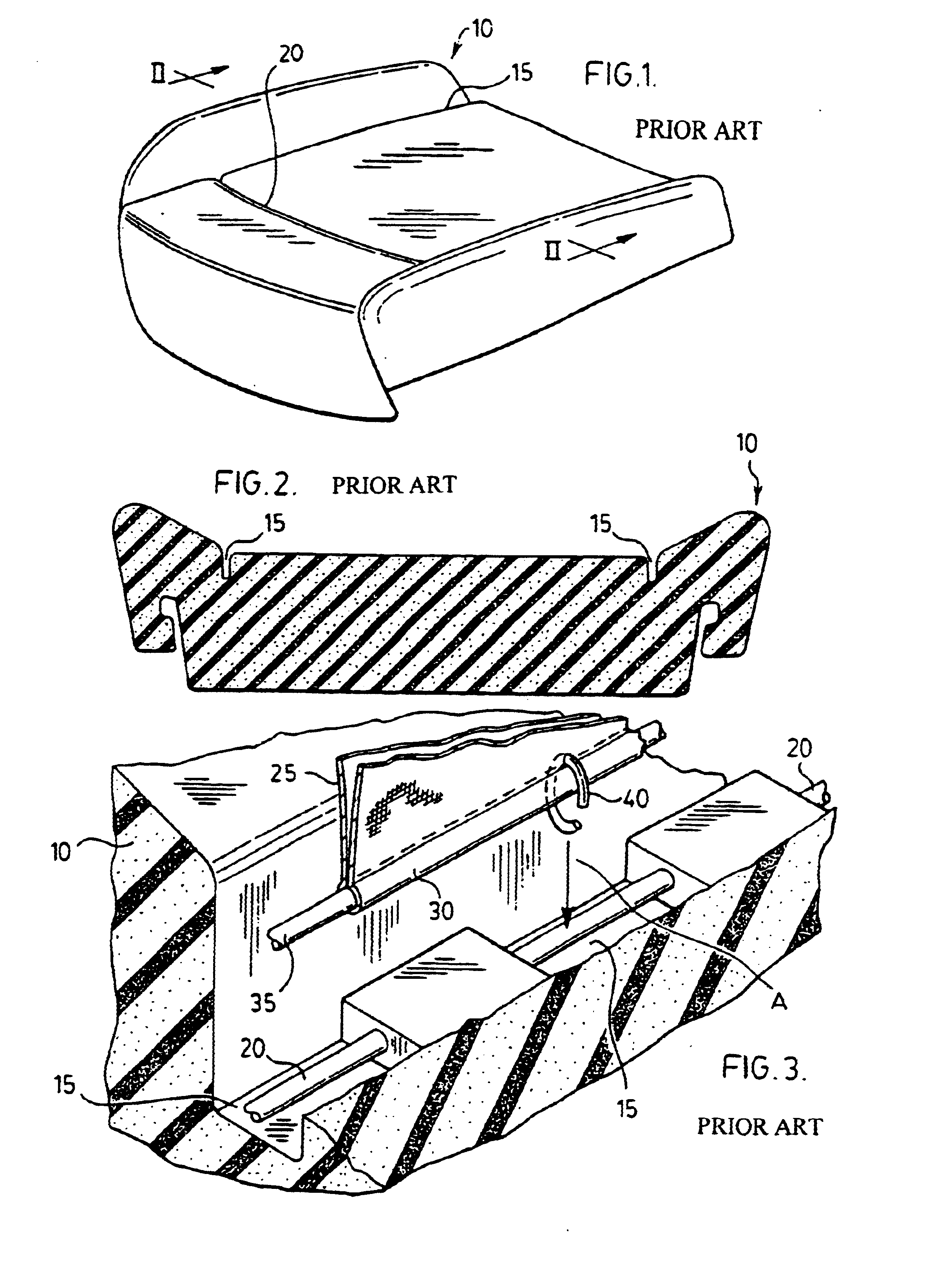
With reference to FIGS. 1 and 2, there is illustrated a foam pad 10, typically used as a seat element in a vehicular seat component.

Typically, foam pad 10 will be molded from a foamable material such as an isocyanate based polymer system or from expanded polymer beads (e.g., polypropylene). For the purposes of the present invention, it is highly preferred that foam pad 10 be molded from an isocyanate-based polymer foam such as polyurethane foam, polyurea foam and the like.

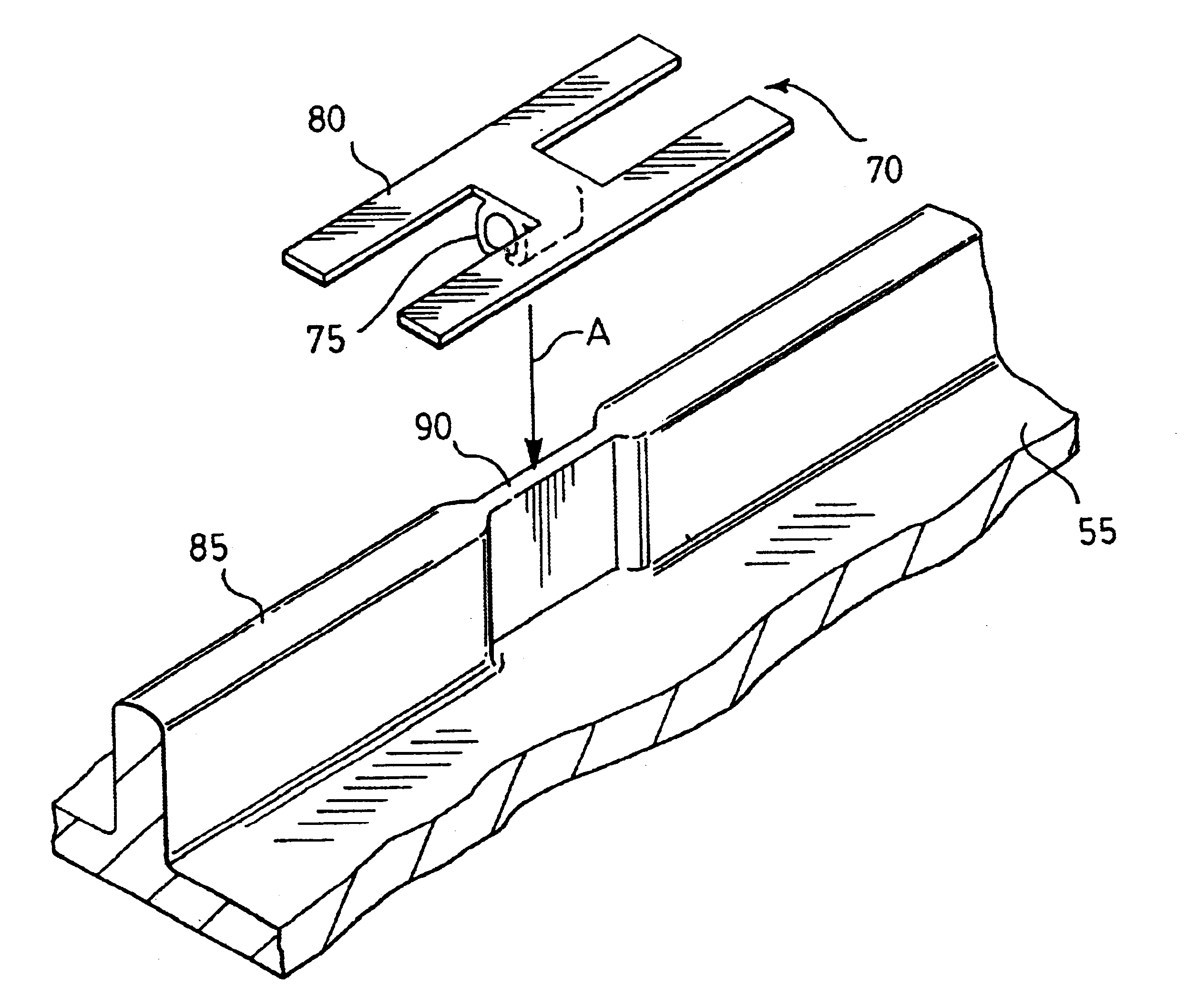
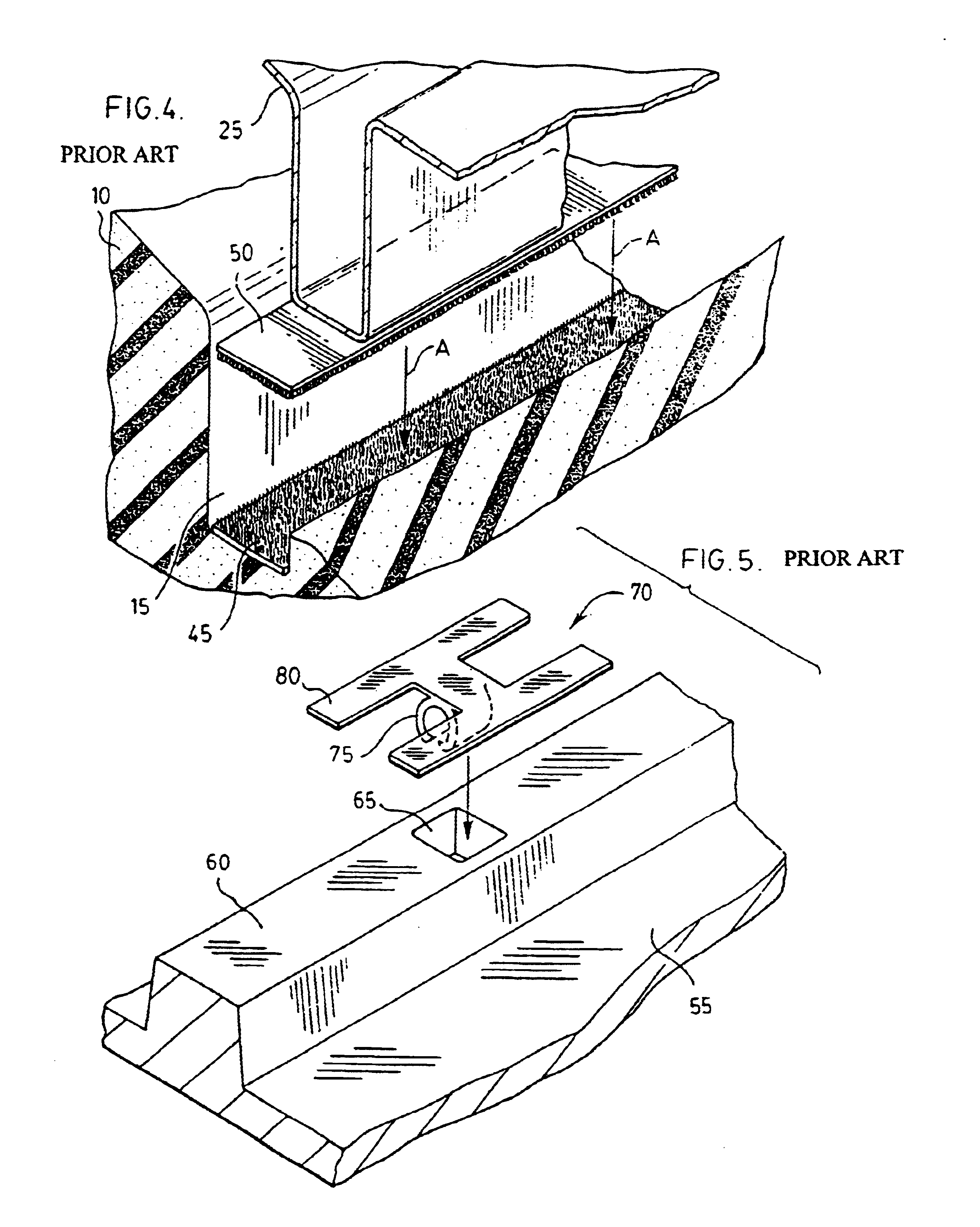
During the molding process, it is common to mold into the surfaces of the foam of the various contours and trenches. Specifically, as shown in FIGS. 1 and 2, foam pad 10 comprises a pair of substantially parallel trenches 15 and a transfer trench 20 which interconnects trenches 15. Trenches 15, 20 are disposed in what is typically referred to as the A-surface of foam pad 10. The underside of foam pad 10 is typically referred to as the B-surface of the foam element. As will be apparent below, trenches 15 and / or 20 c...


PUM

PropertyMeasurementUnit
widthaaaaaaaaaa
widthaaaaaaaaaa
widthaaaaaaaaaa

Abstract

A foam pad comprising a surface to which a trim cover can be secured, the surface comprising a channel having a width of up to about 15 mm. Disposed in the channel is one of a male portion or a female portion of a releasably engageable male-female trim cover attachment system. A trim cover having the other of the male or female portion attached thereto may be readily attached to the foam pad. A process and a mold for producing the foam pad are also described. The foam pad is particularly useful as a component of a vehicular seat system (e.g., seat bottom, seat back and the like).

Description

BACKGROUND OF THE INVENTION1. Field of the InventionIn one of its aspects, the present invention relates to a foam pad, preferably a foam pad for use in a vehicular seat. In another of its aspects, the present invention provides a process for producing such a foam pad.2. Description of the Prior ArtAttachment of a trim cover to a resilient device is generally known.In most cases, the resilient device is a foam device, although, in some cases, a fibrous matrix such as rubberized horsehair and the like is still being employed. Typically, it is desired to secure a trim cover to a resilient device to produce a vehicular seat or a component of a vehicular seat.There are three general categories of approaches in attachment of a trim cover to a resilient device: adhesive, foam-in-place and mechanical. The present invention relates to an improvement falling in the latter category and thus, prior art in this category will be discussed.In the mechanical approach for attachment of a trim cover...

Claims


Application Information

Patent Timeline
Patent Type & Authority Patents(United States)
IPC IPC(8): B60N2/58B60N2/90
CPCB29C44/1271B60N2/5825Y10S5/953Y10T428/24496Y10T428/24008Y10T428/24017Y10T428/24198Y10T428/24711Y10T428/24504Y10T428/24512Y10T428/249953Y10T428/249923
Inventor CAPPUCCI, DEBRA MARIELANSUE, RANDALL JOSEPH
Owner PROPRIETECT LP
Why Eureka
Try Eureka