Device for increasing power of extremely low DC voltage

Active Publication Date: 2005-01-04
ROYNAT CAPITAL
View PDF10 Cites 27 Cited by
  • Summary
  • Abstract
  • Description
  • Claims
  • Application Information

AI Technical Summary

Benefits of technology

It is yet another object of the present invention to provide a heat to electrical power supply conversio

Problems solved by technology

Wiring of an AC source to the receiver of the remote control device is often difficult to make due to the installation location of the gas equipment particularly when the gas equipment is situated in a building having a finished wall construction.
However, the drawback of a battery supply is that the battery requires replacement from time to time as its power depletes, especially when its power would deplete in a much fas

Method used


Image

  • Device for increasing power of extremely low DC voltage
  • Device for increasing power of extremely low DC voltage

Examples


Example

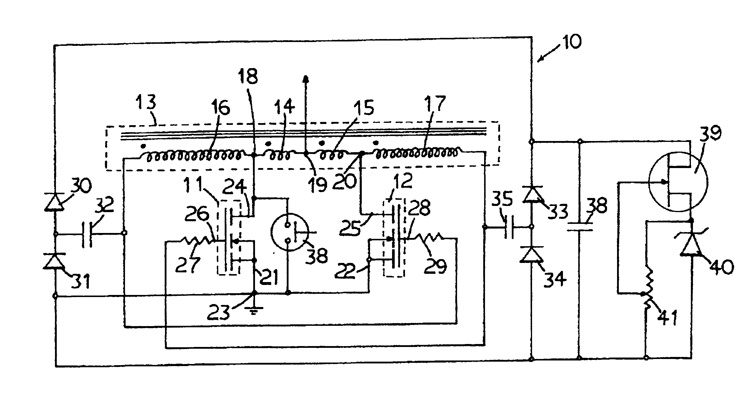
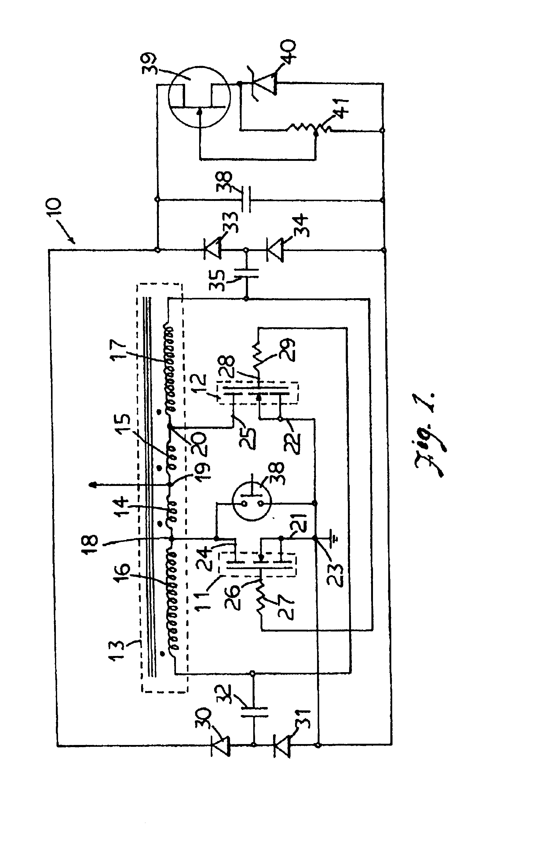
With reference to the drawing, the electronic device 10 of the present invention has an oscillation circuit having two MOSFET transistors 11 and 12 connected in tandem and coupled with a multi-winding transformer 13 which has four bifilar windings 14, 15, 16 and 17. The four bifilar windings are wound on a core having a very high permeability so as to provide a good coupling between the windings. The numbers of windings in windings 14 and 15 are equal to one another and the numbers of windings of windings 16 and 17 are equal to one another and is much higher than those of windings 14 and 15. The start of the winding 14 is connected to the end of the winding 16 at a first connection terminal 18, and the end of the winding 14 is connected to the start of the winding 15 at a second connection terminal 19, whereas the end of the winding 15 is connected to the start of the winding 17 at a third connection terminal 20. The start of the windings 14, 15, 16 and 17 is indicated in the drawin...


PUM


Abstract

A device for increasing an extreme low voltage from a heat to electrical voltage thermopile is shown. The device has an oscillator including two MOSFET transistors coupled to a transformer having four bifilar windings wound on a core having a high permeability. The two transistors operate alternately to generate an intermediate voltage which is increased in magnitude by a voltage doubling and rectifying circuit to obtain the substantially constant operating output voltage. The output voltage is further maintain constant by a current control cirucit including an adjustable potentiometer adjustable to vary the current.

Description

FIELD OF THE INVENTIONThis invention relates to an electronic device for increasing an extremely low DC voltage to a voltage suitable for operating other electronic devices. More particularly it relates to an electronic device usable for increasing the extremely low voltage generated by a transducer which converts heat energy of the flame of a pilot light of a gas equipment such as a gas fireplace and the like to an electrical power suitable for operating the electrical control of the gas supply to the gas equipment.BACKGROUND OF THE INVENTIONThe gas supply to the main burner of a gas equipment is controlled by an electrically operated solenoid valve. Such valve is commonly operated with a voltage supply of 6 to 9 volts DC in order to reduce the potential fire hazard for operating it in the explosive gas environment if it is operated with a higher voltage. The solenoid valve may be actuated with a manual switch or an electronic remote control device. The operating electrical power o...

Claims


Application Information

Patent Timeline
IPC IPC(8): F23N5/02F23N5/10H02M3/24H02M3/338H02M3/04H02M3/156
CPCF23N5/102H02M3/3384H02M3/1563F23N2035/14F23N2235/14
Inventor SHAH, REZA H.
Owner ROYNAT CAPITAL
Why Eureka
Try Eureka