
Shorting switch and system to eliminate arcing faults in power distribution equipment

Inactive Publication Date: 2005-01-04
EATON INTELLIGENT POWER LIMITED
View PDF17 Cites 31 Cited by
  • Summary
  • Abstract
  • Description
  • Claims
  • Application Information

AI Technical Summary

Benefits of technology

These needs and others are met by the present invention, which provides a high-speed shorting switch that can extinguish an arcing fault in switchgear. This switch is a low cost, one-shot, replaceable module that can be installed, for example, on the load side of a circuit breaker to allow selective tripping.
The switch may employ two spring-loaded contacts held apart by the insulator. The charge, such as a high-pressure generator, may drive the slug between the contacts, driving out the insulator, and shorting out the contacts. The contact geometry and relatively high spring force may keep the slug in good electrical contact with the contacts during the relatively high arcing fault current flow.

Problems solved by technology

There is the potential for an arcing fault to occur across the power bus of a motor control center (MCC), another low voltage (LV) enclosure (e.g., an LV circuit breaker panel) and other industrial enclosures containing LV power distribution components.
Frequently, a worker inadvertently shorts out the power bus, thereby creating an arcing fault inside the enclosure.
The resulting arc blast creates an extreme hazard and could cause injury or even death.
This problem is exacerbated by the fact that the enclosure doors are typically open for maintenance.
Such switches, which are large and costly, are located on the main power bus to shut down the entire power bus system when a fault occurs even if the fault is only on the load side of a branch circuit.
The resulting short on the power bus causes an upstream circuit breaker to clear the fault.

Method used


Image

  • Shorting switch and system to eliminate arcing faults in power distribution equipment
  • Shorting switch and system to eliminate arcing faults in power distribution equipment
  • Shorting switch and system to eliminate arcing faults in power distribution equipment

Examples


Embodiment Construction

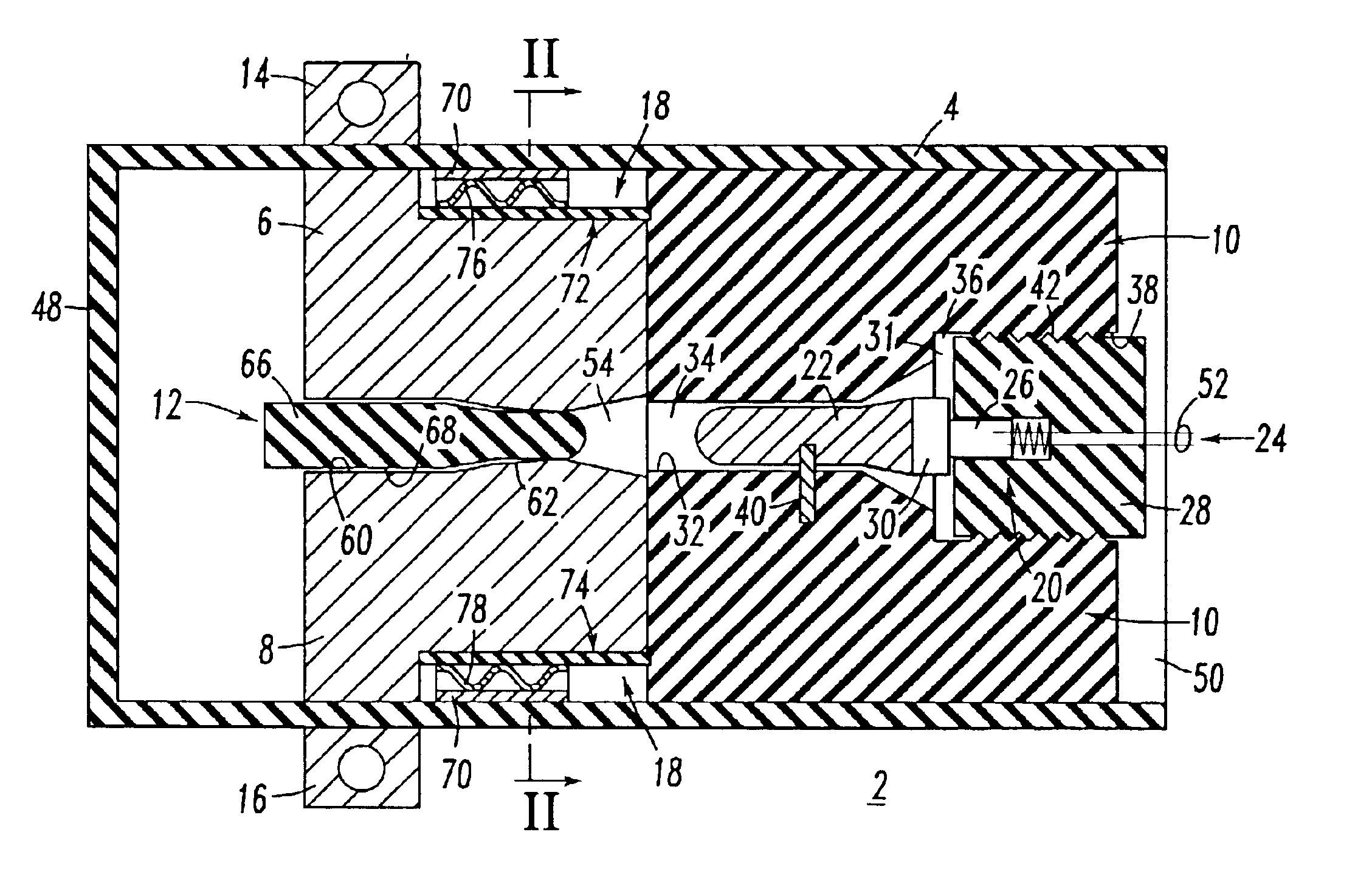
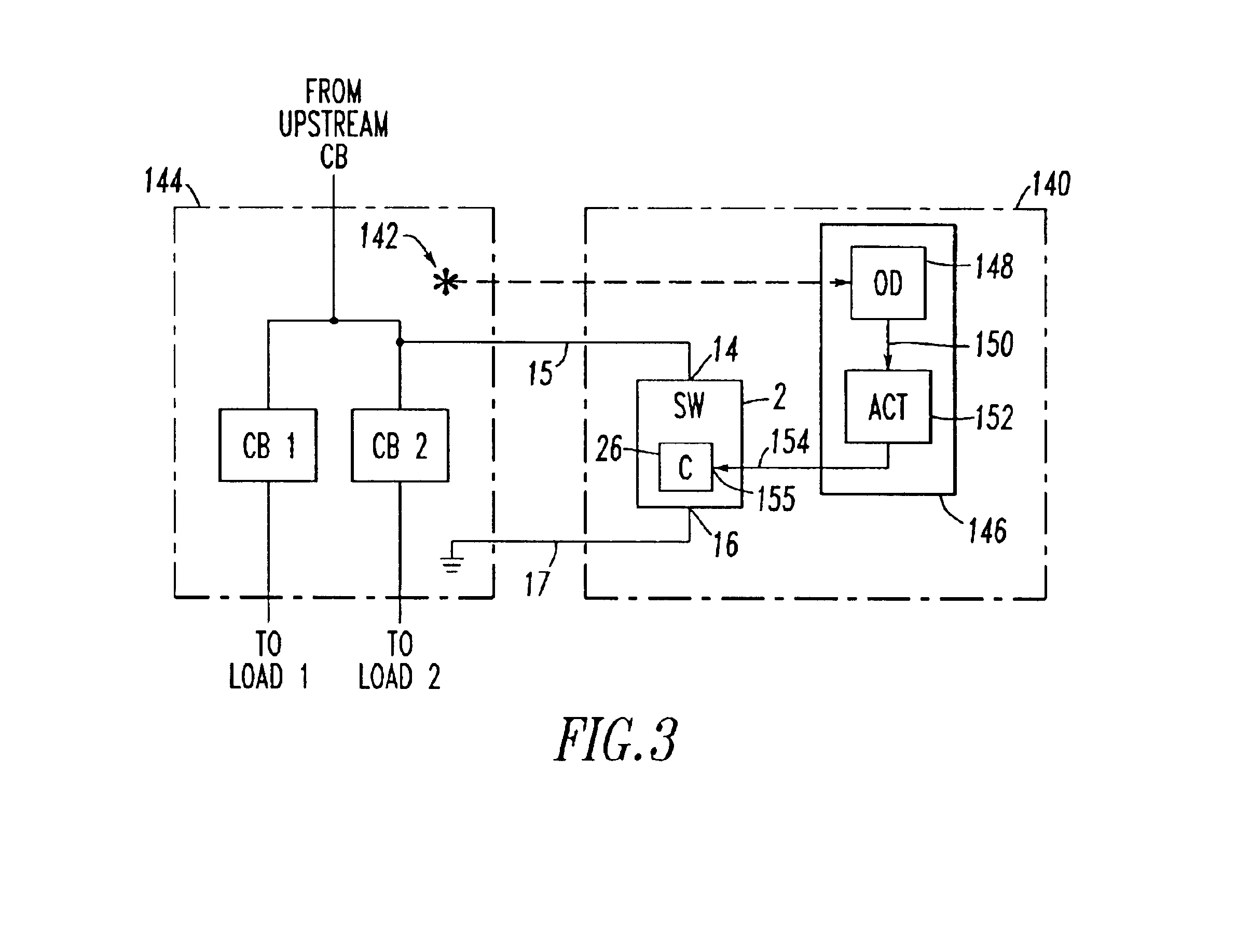
FIG. 1 shows a high-speed low voltage shorting switch 2 employing a combination of solid and gas (e.g., air) insulation. The exemplary shorting switch 2 is a relatively low cost, one-shot, crowbar switch, which advantageously eliminates arcing faults in low voltage power distribution equipment (not shown). The shorting switch 2 is activated (as discussed below in connection with FIG. 3) when an arcing fault is detected.

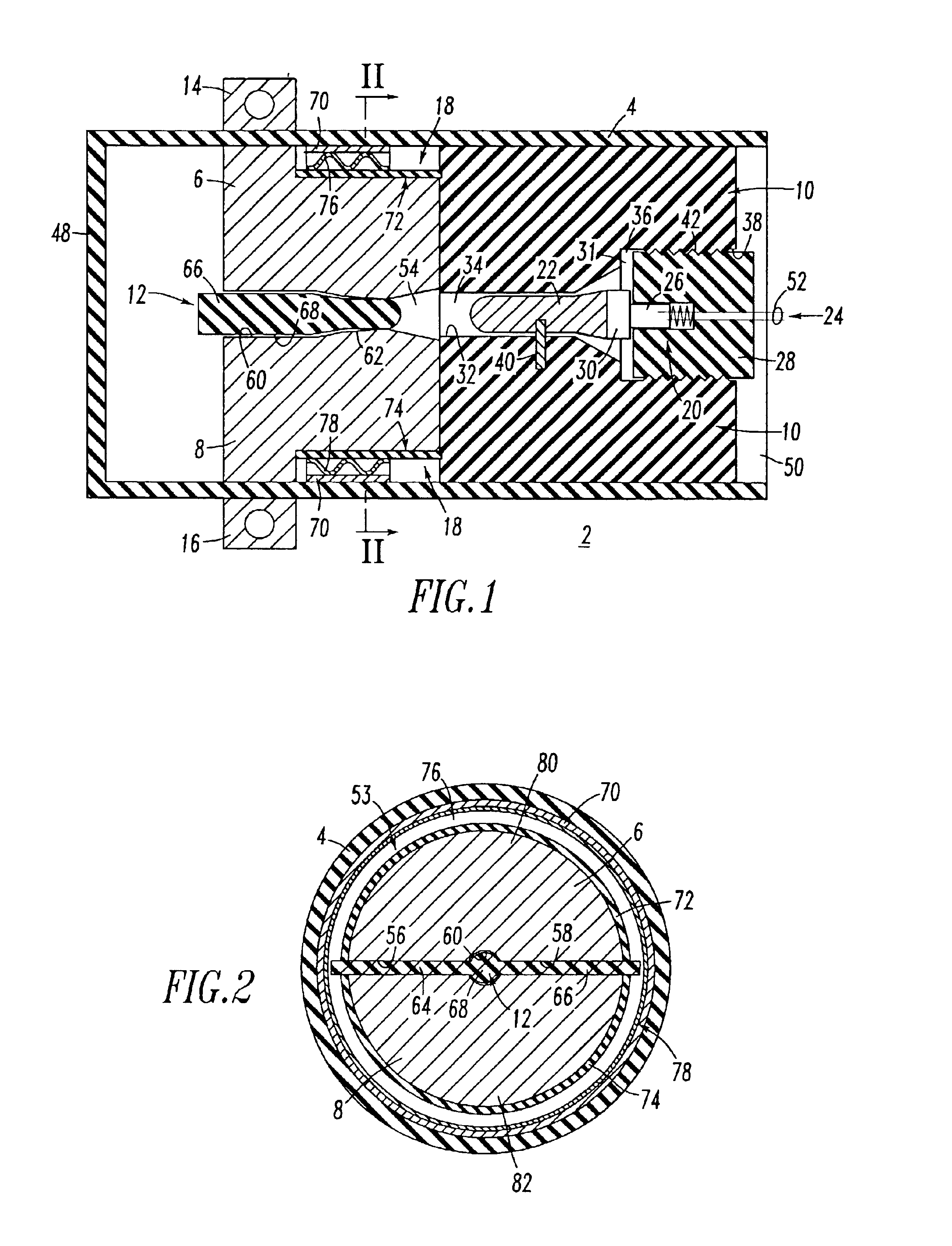
The shorting switch 2 includes an insulating housing, such as insulating tube 4, a first contact 6, a second contact 8, a first insulator 10, and a second insulator 12. Any suitable solid insulator (e.g., thermal set polyester; a thermal plastic, such as Delrin or Nylon) may be employed in the exemplary insulating tube 4 and / or insulators 10,12. Any suitable conductor (e.g., copper) may be employed for the contacts 6,8. The second insulator 12 is between the first and second contacts 6,8 in the insulating tube 4, in order to normally prevent electrical connection of s...


PUM


Abstract

A shorting switch eliminates arcing faults in power distribution equipment. The shorting switch includes an insulating tubular housing; a first contact; a second contact; and an insulator between the first and second contacts in the insulating housing. The insulator prevents electrical connection of the first and second contacts. First and second terminals are respectively electrically connected to the first and second contacts. A wave spring mechanism moves the first and second contacts toward closure. A slug and an activated charge mechanism drive the insulator from between the first and second contacts, in order to electrically connect the first and second contacts.

Description

BACKGROUND OF THE INVENTION1. Field of the InventionThe invention is directed to shorting switches and, in particular, to shorting switches for eliminating arcing faults in power distribution equipment. The invention is also directed to shorting systems for eliminating arcing faults in power distribution equipment.2. Background InformationThere is the potential for an arcing fault to occur across the power bus of a motor control center (MCC), another low voltage (LV) enclosure (e.g., an LV circuit breaker panel) and other industrial enclosures containing LV power distribution components. This is especially true when maintenance is performed on or about live power circuits. Frequently, a worker inadvertently shorts out the power bus, thereby creating an arcing fault inside the enclosure. The resulting arc blast creates an extreme hazard and could cause injury or even death. This problem is exacerbated by the fact that the enclosure doors are typically open for maintenance.It is known...

Claims


Application Information

Patent Timeline
IPC IPC(8): H01H39/00
CPCH01H39/004
Inventor SHEA, JOHN J.CHIEN, YUN-KO N.
Owner EATON INTELLIGENT POWER LIMITED
Learn More