

Developer supply container
- Summary
- Abstract
- Description
- Claims
- Application Information
AI Technical Summary
Benefits of technology
Problems solved by technology
Method used
Image

Examples
first embodiment
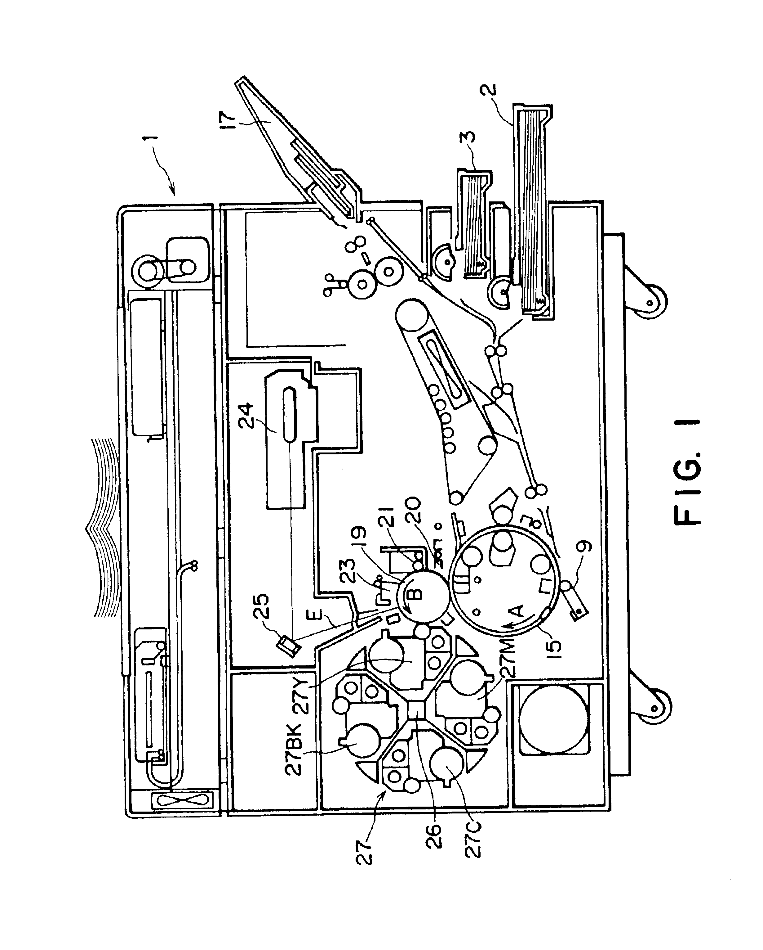
Referring to FIG. 1-FIGS. 7(a) through 7(c), and description will first be made as to an image forming apparatus of a first embodiment usable with a developer container according to an embodiment of the present invention. The image forming apparatus 1 to which the developer container according to an embodiment of the present invention is mountable, comprises image forming means including a photosensitive drum 19 (latent image forming station). An outer surface of the photosensitive drum 19 is contacted to a transfer drum 15, and the photosensitive drum 19 is rotatable in a direction indicated by arrow B in FIG. 1
Around the outer surface of the photosensitive drum 19, there are provided a discharging charger 20, cleaning means 21 and a primary charger 23 in the order named in the rotational direction of the photosensitive drum 19. There are also provided image exposure means 24 in the form of a laser beam scanner for example for forming an electrostatic latent image on the outer surf...
embodiment 1
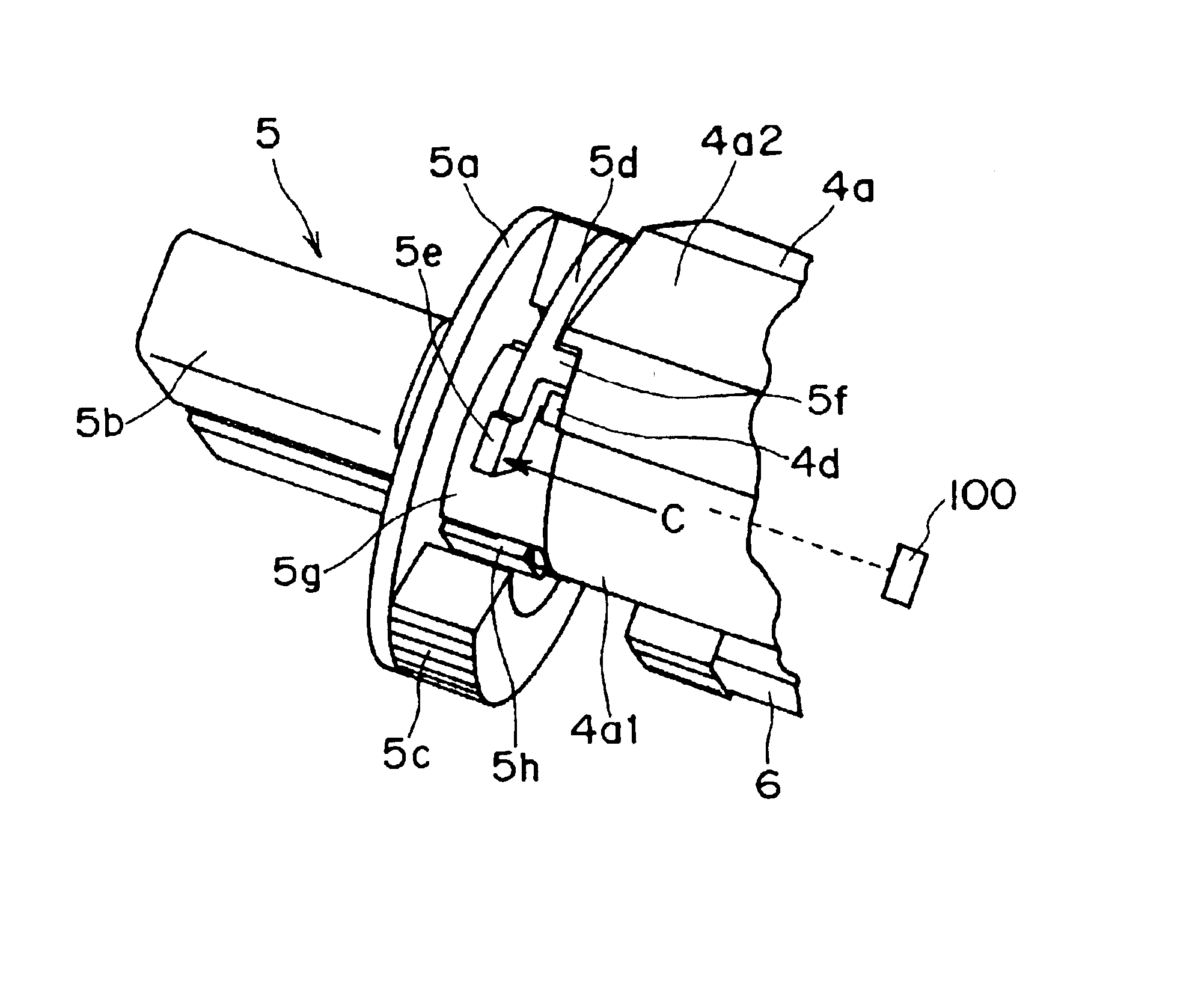
However, if the main body side of the developer container 4 is constituted by a recess, the following is to be taken into consideration. That is, when the developer accommodating portion 4a is constituted by two parts (upper portion material 4a1 and lower portion material 4a2) , a metal mold structure for the member having the recess may be complicated because the necessity may arise for a so-called inner slide.
In the foregoing embodiments, the arm portion 5d which displaces between the looking position and the releasing position is provided on the arm portion 5d, but it is a possible alternative that arm portion or another displaceable member may be provided on the developer container 4 side.
More particularly, in the foregoing embodiments, the locking engaging portion 5f (locking portion) is provided on the knob 5 side, and the portion to be locked 4d (portion to be locked) is provided on the main body side of the developer container 4. However, the locking portion may be provided ...
PUM
 Abstract
Description
Claims
Application Information