
Method and apparatus for vending machine controller configured to monitor and analyze power profiles for plurality of motor coils to determine condition of vending machine

Inactive Publication Date: 2005-01-04
LOGICLINK CORP
View PDF11 Cites 104 Cited by
  • Summary
  • Abstract
  • Description
  • Claims
  • Application Information

AI Technical Summary

Benefits of technology

In one embodiment, the present invention is an apparatus which includes an electrically powered device having a key operating line and

Problems solved by technology

Such an approach to monitoring the status of electrically powered equipment for the purpose of generating billing is deficient in that it is highly complicated, requires bi-directional communications, and cannot readily be adjusted to compensate for changes in the communication interfaces and interface hardware of the monitored devices.
Current technology employing alternating current (“A / C”) lines is deficient in that it does not provide bi-directional feedback.
Although it is known to functionally connect an electrically powered device to a mechanism for receiving payment, the art is devoid of a self-service system which allows multiple users to simultaneously select, activate, and prepay for the use of groups of electrically powered devices.
However, one problem with charging a user based on the amount a device is used is that if such device hangs up, jams, or is otherwise not operating properly, the user will still be charged for the time.

Method used


Image

  • Method and apparatus for vending machine controller configured to monitor and analyze power profiles for plurality of motor coils to determine condition of vending machine
  • Method and apparatus for vending machine controller configured to monitor and analyze power profiles for plurality of motor coils to determine condition of vending machine
  • Method and apparatus for vending machine controller configured to monitor and analyze power profiles for plurality of motor coils to determine condition of vending machine

Examples


Embodiment Construction

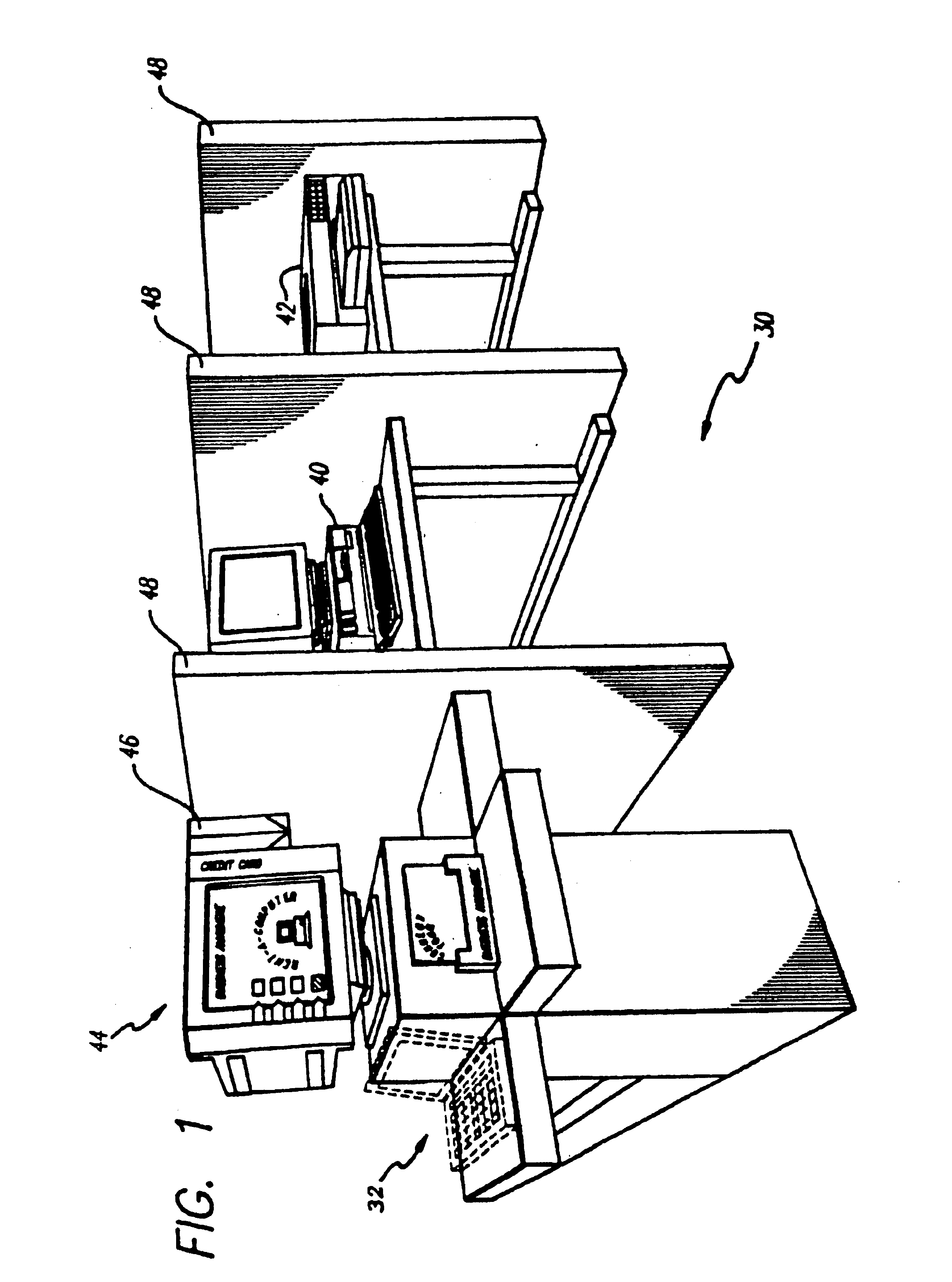
FIG. 1 shows an exemplary system 30 for interactively selecting and activating one or more electrically powered devices. In this embodiment, the system 30 includes one or more computers 40 and / or one or more computer peripheral devices (e.g., printer 42). While the exemplary system 30 includes computers, computer peripherals, and / or other devices typically found in an office, it is contemplated that the one or more electrically powered devices could include appliances such as, for example, a television or coffee maker.

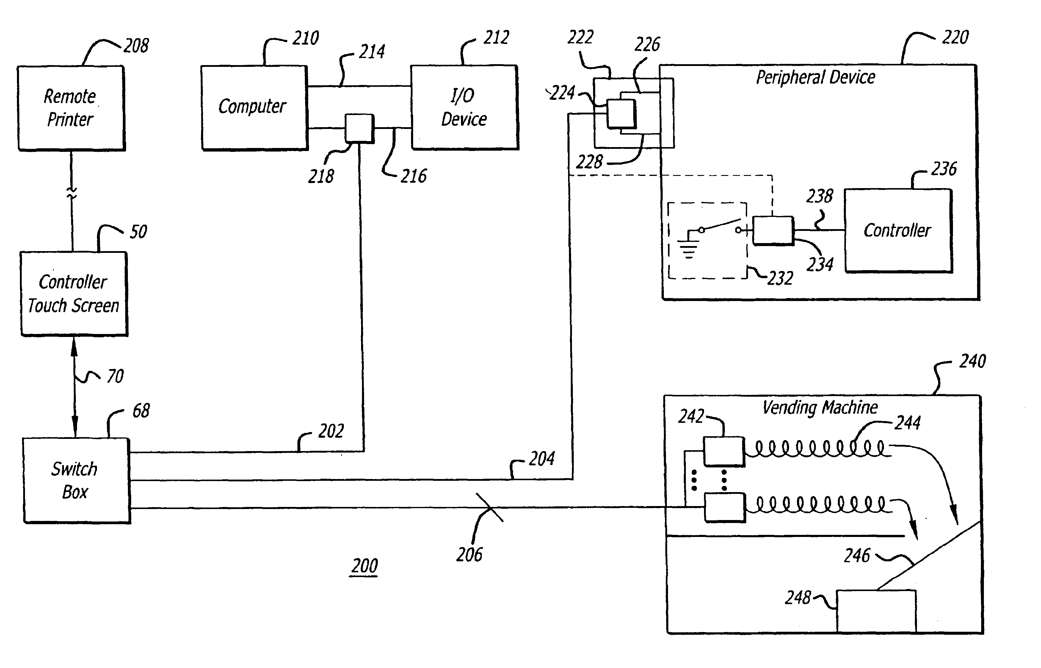
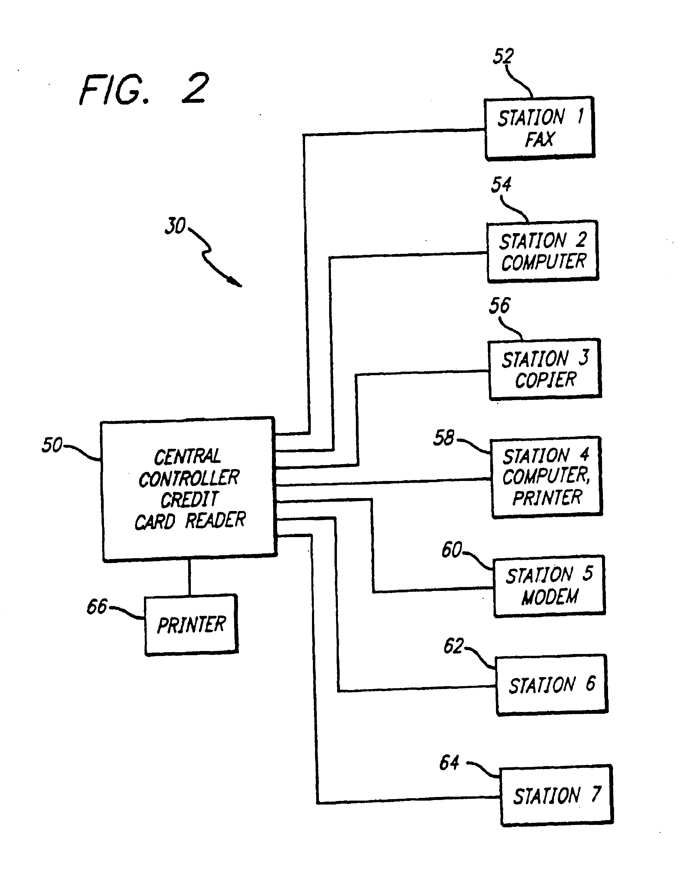
The system 30 additionally includes a display 44 which comprises a video monitor as shown in this embodiment. The system 30 may also include a mechanism for receiving payment, such as, for example, a card reader 46 for obtaining information from a credit card, pre-paid debit card, smart card, membership card, room key, or any other type of card. Alternatively, the mechanism for receiving payment can take another form such as a coin and / or currency receiving mechanism, ...


PUM


Abstract

An apparatus for selecting, monitoring, and controlling electrically powered devices is disclosed. In one embodiment, the apparatus includes an electrically powered device having a key operating line and switching control circuitry to control usage of the electrically powered device by interrupting continuity of the key operating line. In another embodiment, the apparatus monitors usage of an electrically powered device. The apparatus includes a circuit which is coupled to the device to provide a power output of the device, an analog to digital converter coupled to receive the power output and convert the same to digital form, and a controller to receive a user input, process the user input by establishing communication with a remotely located device to request approval of a financial transaction, and generate control signals in response to receiving approval. The controller receives the digital form of the power output and monitors the operation of the electrically powered device.

Description

BACKGROUND OF THE INVENTION1. Field of the InventionThe present invention relates generally to a method and apparatus for selecting, monitoring, and controlling electrically powered devices.2. Background InformationA known approach to monitoring the usage of computers and peripheral devices is through a network. Such an approach to monitoring the status of electrically powered equipment for the purpose of generating billing is deficient in that it is highly complicated, requires bi-directional communications, and cannot readily be adjusted to compensate for changes in the communication interfaces and interface hardware of the monitored devices.In addition to monitoring usage of computers and computer peripheral devices, it is desirable to be able to remotely activate and deactivate such devices. Current technology employing alternating current (“A / C”) lines is deficient in that it does not provide bi-directional feedback.Known computer rental outlets (e.g., such as Kinkos™) depend u...

Claims


Application Information

Patent Timeline
IPC IPC(8): G06F1/26G06F11/34
CPCG06F1/26G06F11/3409G06F1/266
Inventor KAO, KIM Y.SAUER, BRUCE K.KWAN, KENT
Owner LOGICLINK CORP
Features
  • Generate Ideas
  • Intellectual Property
  • Life Sciences
  • Materials
  • Tech Scout
  • Unparalleled Data Quality
  • Higher Quality Content
  • 60% Fewer Hallucinations
Learn More