Disk array control device with an internal connection system for efficient data transfer

a control device and data transfer technology, applied in the direction of memory address/allocation/relocation, input/output to record carriers, instruments, etc., can solve the problems of low data transfer rate, low data transfer efficiency, and difficulty in identifying the error-detection channel if unit (or disk if unit), so as to achieve high data transfer throughput and use every access path efficiently

Inactive Publication Date: 2005-01-04
HITACHI LTD
View PDF11 Cites 10 Cited by
  • Summary
  • Abstract
  • Description
  • Claims
  • Application Information

AI Technical Summary

Benefits of technology

Under the circumstances, it is an object of the present invention to provide a disk array controller that can solve the above problems, that can make it possible to use every access path efficiently between each of the channel IF units and / or the disk IF units and a cache memory, and that will include a cache memory unit having a high throughput of data transfer.

Problems solved by technology

For a disk array controller that employs the shared bus connection form, however, increasing the number of channel IF units and disk IF units degrades the data transfer throughput of the access path between each of the channel IF units and / or the disk IF units and a cache memory unit or a shared memory unit which is to become scalable according to an increase in the number of channel IF units or disk IF units.
This is because the shared bus becomes a bottleneck in making the access path throughput scalable.
Furthermore, in the case of the shared bus connection form, if a high performance microprocessor is employed for each of those channel IF units and / or the disk IF units, the transfer capacity of the shared bus cannot cope with the processor performance, thereby the shared bus can hardly keep up with the high speed operation of the processor.
Furthermore, in the case of the shared bus connection form, if an operation error occurs in any of those channel IF units (or disk IF units) connected to the shared bus, it is difficult to identify the error-detected channel IF unit (or disk IF unit).
For this reason, increasing the line number of access paths between the channel and disk IF units and the cache memory unit would result in creation of a problem of shortage of the number of pins in an LSI(s) of the cache memory unit and shortage of the number of pins in a connector of the cache memory unit package for connection of the access paths thereof.

Method used


Image

  • Disk array control device with an internal connection system for efficient data transfer
  • Disk array control device with an internal connection system for efficient data transfer
  • Disk array control device with an internal connection system for efficient data transfer

Examples


Embodiment Construction

Hereunder, the preferred embodiments of the disk array controller of the present invention will be described with reference to the accompanying drawings.

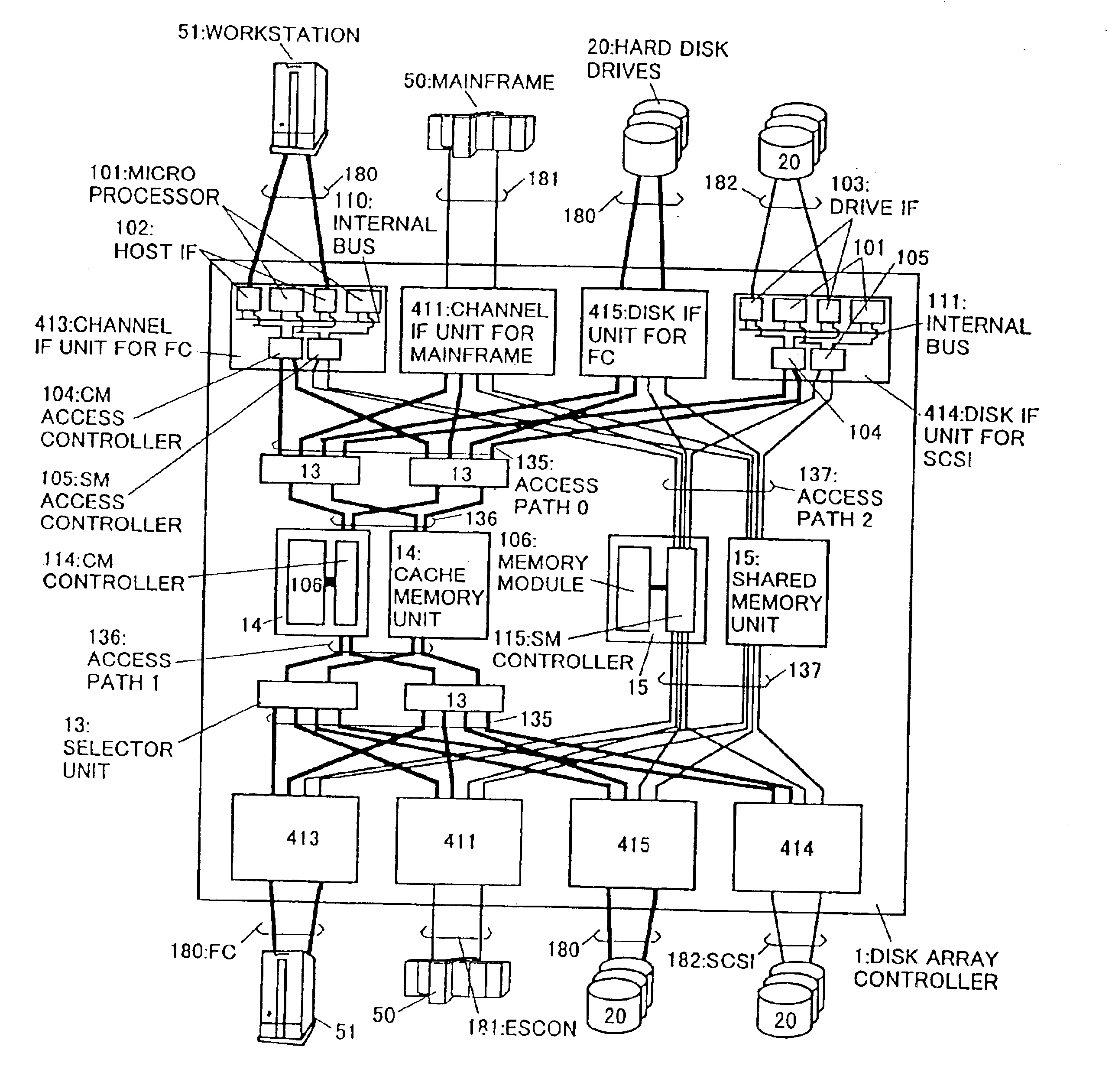
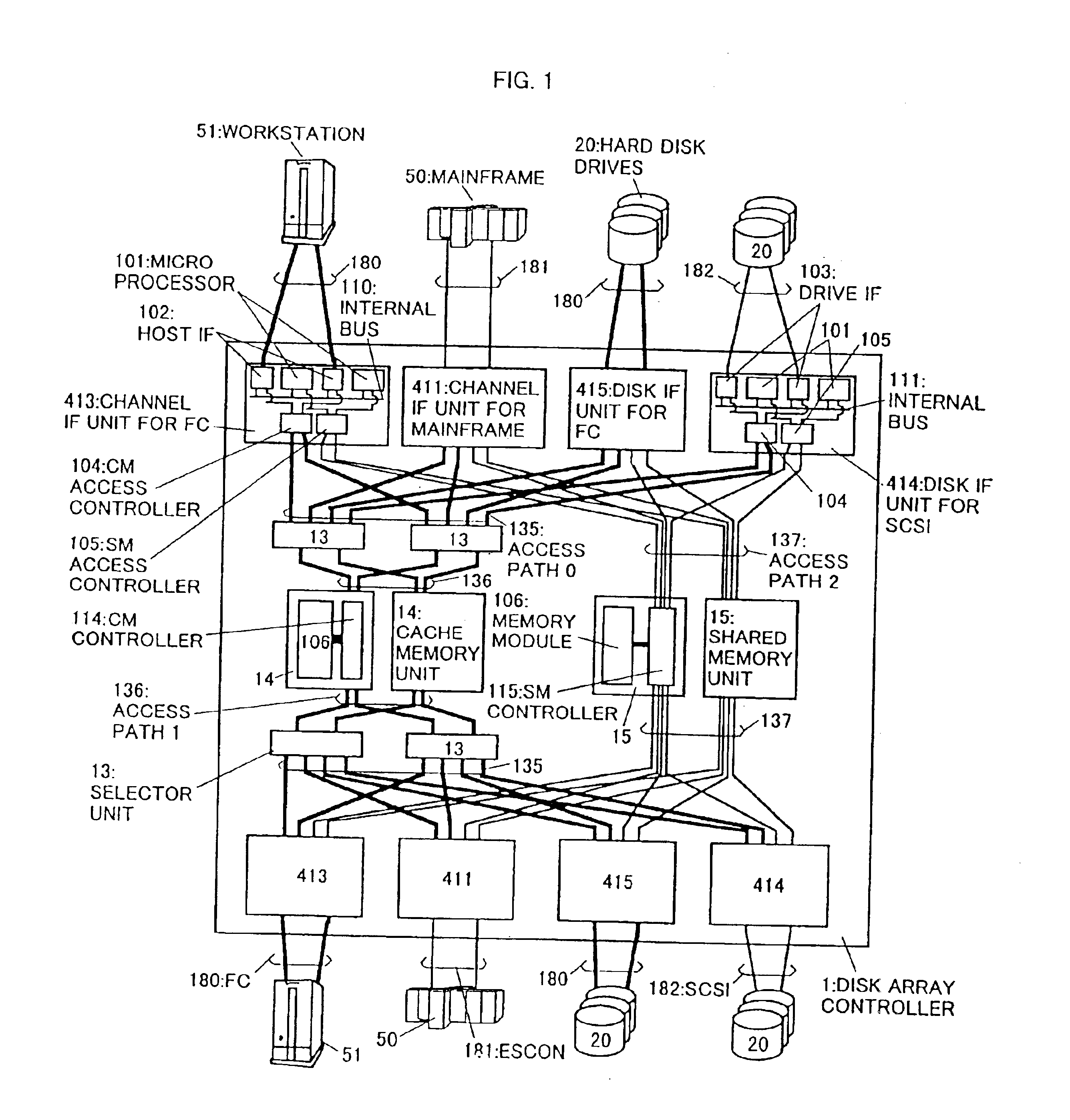
FIG. 1 is a block diagram of a disk array controller representing an embodiment of the present invention.

The disk array controller 1 is mainly composed of two channel IF units 411 for connecting two main frames 50; two channel IF units 413 for FCs (Fiber Optic Channels) for connecting two work stations 51; two disk IF units for SCSI 414 for connecting magnetic disk units 20; two disk IF units for FC 415 for connecting magnetic disk units 20; four selector units 13; two cache memory units 14; two shared memory units 15; access paths 0:135; access paths 1:136; and access paths 2:137. In this embodiment, the access paths 0:135 and the access paths 1:136 are assumed to be all equal in bandwidth per line (for example, 200 MB / sec). Hereafter, both of the main frame 50 and the work station 51 may be referred to as host computers for conven...


PUM


Abstract

A disk array controller which includes a channel interface unit for connecting a host computer through a first type channel, a channel interface unit for connecting a host computer through a second type channel, a plurality of disk interface unit provided with an interface with a magnetic disk unit respectively, a cache memory unit, and a shared memory unit. The number of access paths connected to said cache memory unit is less than the number of access paths connected to the shared memory unit.

Description

BACKGROUND OF THE INVENTIONThe present invention relates to control devices of disk array devices for storing data in a plurality of magnetic disk devices.In view of the fact that the input / output (I / O) performance or throughput of a disk subsystem (referred to as a “subsystem” hereinafter) is less by approximately three to four orders of magnitude than the I / O throughput of main memories of computers which use semiconductor memory devices as their storage media, attempts have conventionally been made to reduce this difference, namely, to improve the I / O throughput of the subsystem. One prior known approach to improving the subsystem's I / O throughput is to use a system, called a “disk array”, for constituting the subsystem from a plurality of magnetic disk devices, such as fixed or “hard” disk drives (HDDs), which are applicable for use in storing data.FIG. 2 shows an arrangement typical of one known type of disk array. This includes a plurality of channel interface (IF) units 411 f...

Claims


Application Information

Patent Timeline
Patent Type & Authority Patents(United States)
IPC IPC(8): G06F3/06G06F12/08
CPCG06F3/0607G06F3/061G06F3/0613G06F3/0635G06F3/0658G06F12/0866G06F3/0661G06F3/067G06F3/0683G06F3/0689G06F3/0659
Inventor FUJIMOTO, KAZUHISATANAKA, ATSUSHIFUJIBAYASHI, AKIRA
Owner HITACHI LTD
Why Eureka
Try Eureka