System for clock synchronization

a clock synchronization and system technology, applied in multiplex communication, generating/distributing signals, instruments, etc., can solve the problems of occupying valuable space in the ne, and affecting the network performance of clients b and

Inactive Publication Date: 2005-01-04
CIENA
View PDF4 Cites 36 Cited by
  • Summary
  • Abstract
  • Description
  • Claims
  • Application Information

AI Technical Summary

Benefits of technology

The present invention includes a synchronization system for providing timing synchronization signals required by line cards in an NE. In one embodiment, the synchronization system is located directly on the line cards so that the need for dedicated timing cards in the NE is eliminated. For example, the synchronization system is located on ADM cards associated with a specific client to prov...

Problems solved by technology

Furthermore, the centralized timing card includes expensive components and takes up valuable space in the NE.
However, line cards operating on data for clients B and C may have to be adjusted to synchronize to the timing reference provided by client A. Therefore, it may be necessary for th...

Method used


Image

  • System for clock synchronization
  • System for clock synchronization
  • System for clock synchronization

Examples


Embodiment Construction

The present invention includes a synchronization system for providing timing synchronization signals required by line cards in an NE used in an optical network. For example, the NE may be one of many NEs used in a Synchronous Optical Network (SONET) and the line cards in the NEs may be ADM transport cards. In one embodiment, the synchronization system is located directly on the line cards so that the need for dedicated timing cards to provide centralized timing in the NE is eliminated. This saves costs and frees up valuable space in the NE. Various embodiments of the synchronization system included in the present invention are discussed in detail in the following text.

Exemplary Embodiment

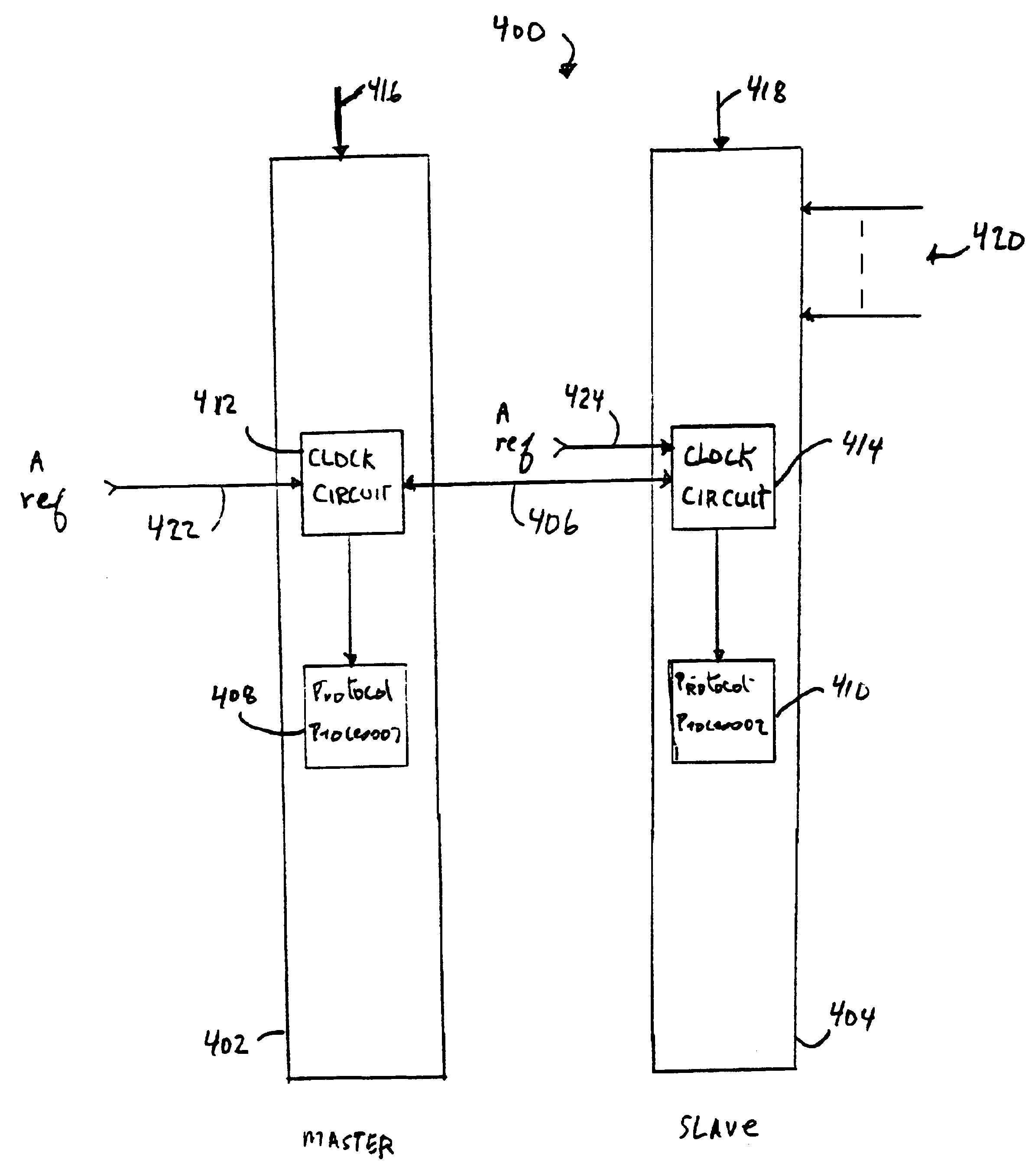
FIG. 4 shows line cards 400 forming a two card ADM protection pair that include one embodiment of a synchronization system in accordance with the present invention. The ADM cards including the synchronization system are suitable for use as line cards in an NE that is part of an optical network, for ...


PUM


Abstract

A timing circuit for use with transport logic in a network element is provided. The network element forms part of a data network and the timing circuit includes a timing receiver having a timing input, a timing output, and a selection input, the timing receiver operable to receive one or more timing signals at the timing input and to select a selected timing signal for distribution to the transport logic via the timing output based on a selection signal received at the selection input. The timing circuit also includes a determination circuit that is operable to determine whether the timing circuit is one of a master timing circuit and slave timing circuit, and based on the determination, produce the selection signal. A sync transmitter is also included in the timing circuit. The sync transmitter is coupled to the timing output, the determination circuit, and a communication channel. The sync transmitter is operable to receive the selected timing signal and to transmit the selected timing signal on the communication channel when the determination circuit determines that the timing circuit is the master timing circuit.

Description

FIELD OF THE INVENTIONThe present invention relates to timing synchronization in a data network, and more particularly, to a synchronization system for providing clock synchronization to transport logic in a network element of an optical network.BACKGROUND OF THE INVENTIONOptical networks are becoming widely used for distributing both high and low speed data over varying distances. Typically, an optical network is comprised of a number of network elements (NE) that are connected to each other in a variety of configurations so as to form a unified communication network. The communication network may extend over a small area, such as a company wide network, or may cover large distances, such as in regional or nationwide networks. Typically, the NE's allow network clients to input data for transmission over the network and to receive data transmitted over the network from other locations. Thus, data may be added or dropped from the network at NE locations as the data flows from point t...

Claims


Application Information

Patent Timeline
IPC IPC(8): H04J3/06
CPCH04J3/0688
Inventor JAMES, MICHAELRYHORCHUK, KENT
Owner CIENA
Why Eureka
Try Eureka