
Flow amount measuring apparatus

a technology of flow amount and measuring apparatus, which is applied in the direction of volume/mass flow measurement, measurement devices, instruments, etc., can solve the problems of inability to adjust the output, product price increase, and deviation of output characteristics, so as to achieve stable output characteristics and less cost. , the effect of convenient operation

Inactive Publication Date: 2005-01-11
DENSO CORP
View PDF9 Cites 15 Cited by
  • Summary
  • Abstract
  • Description
  • Claims
  • Application Information

AI Technical Summary

Benefits of technology

It is still another object of the present invention to provide a flow amount measuring apparatus capable of adjusting output easily.
According to this arrangement, when the potential level on one of the middle junction point in the bridge circuit is increased in accordance with a flow amount, the potential level on the other one of the middle junction points is decreased. Therefore, by applying a differential amplification on both the potential level on the middle junction points by an amplifier circuit, it is possible to achieve large output. As a result, it is possible to decrease the amplitude ratio of the amplifier circuit, that is, a gain.
In addition to the advantage above, or instead thereof, it is possible to adjust the output of the differential amplification to substantially 0 volt when the flow amount is 0. As a result, it is possible to lower an adjusting accuracy required for obtaining a predetermined offset. Therefore, it is easy to adjust the output in manufacturing process.
According to this arrangement, it is possible to adjust offset in accordance with the temperature of fluid. As a result, it is possible to achieve a stable output characteristic regardless of changing in the temperature of fluid. In addition, it is possible to perform the offset adjustment at less cost and in an easier manner. For example, it is possible to perform the adjustment so as to suppress a difference of the output characteristic of each product.

Problems solved by technology

Therefore, it was not easy to adjust the output.
However, due to an expensive laser trimming machine, product price is also increased.
Therefore, the output characteristic may deviate during manufacturing process after the trimming process.
For such purpose, the electrical trimming method has a disadvantage that it is not able to measure flow amount accurately.

Method used


Image

  • Flow amount measuring apparatus
  • Flow amount measuring apparatus
  • Flow amount measuring apparatus

Examples


first embodiment

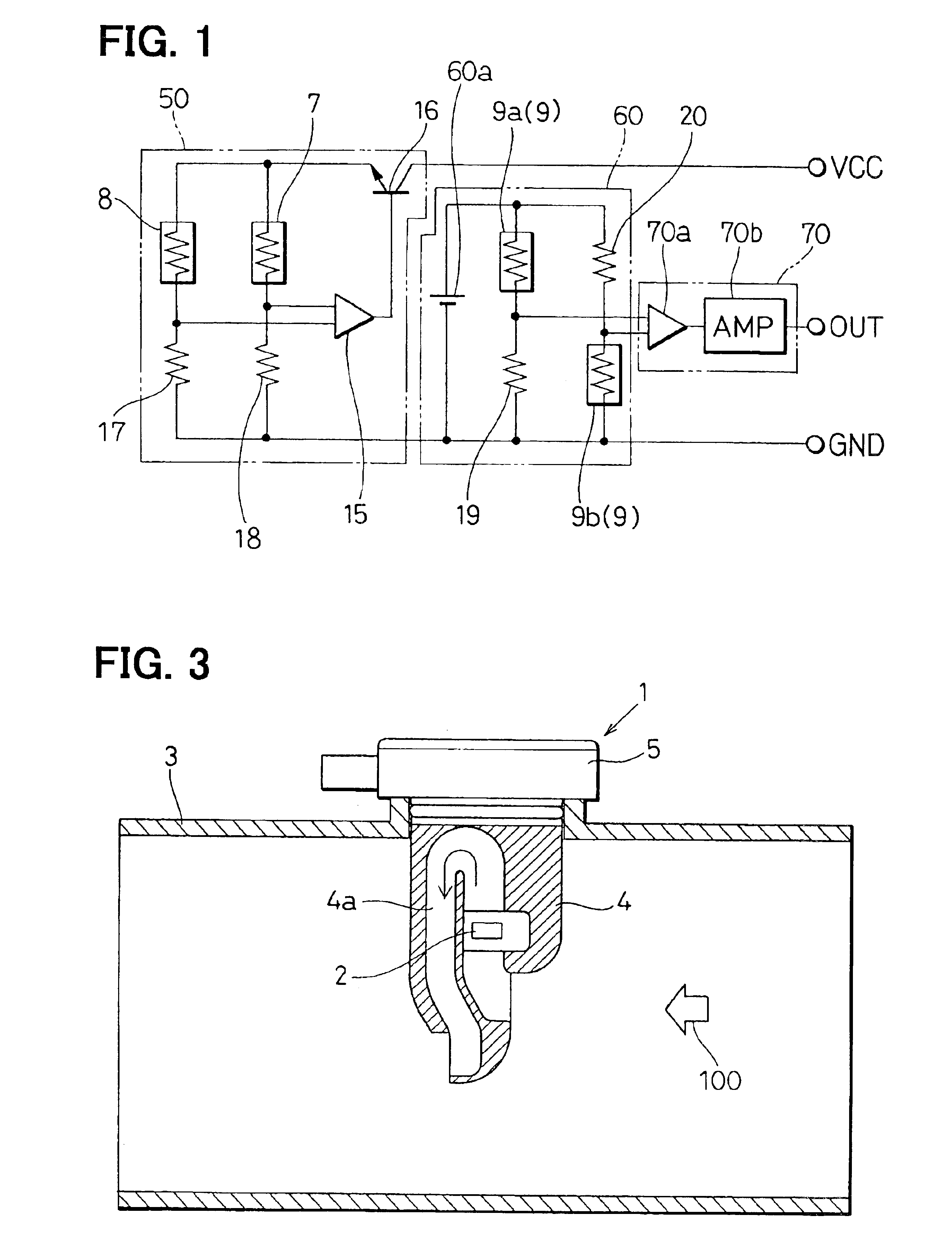
In this embodiment, the flow amount measuring apparatus of the present invention is applied to an airflow meter 1 for measuring flow amount of intake air of internal combustion engine. As shown in FIG. 3, the airflow meter 1 is attached on an intake pipe 3 of the internal combustion engine. the airflow meter 1 has a sensor body 4 made of resinous material and a circuit unit 5. A sensor 2 is supported on the sensor body 4. An electric circuit is mounted on the circuit unit 5, and is electrically connected with the sensor 2 via signal lines, e.g., a printed circuit. The sensor body 4 is attached so as to protrude into the intake pipe 3. The sensor body 4 provides a substantially U shaped bypass passage 4a in which a part of intake air in the intake pipe 3 flows. The bypass passage 4a is a fluid passage through which air as fluid subject to measuring flows. The sensor 2 is located in the bypass passage 4a, and is exposed to air flowing there through.

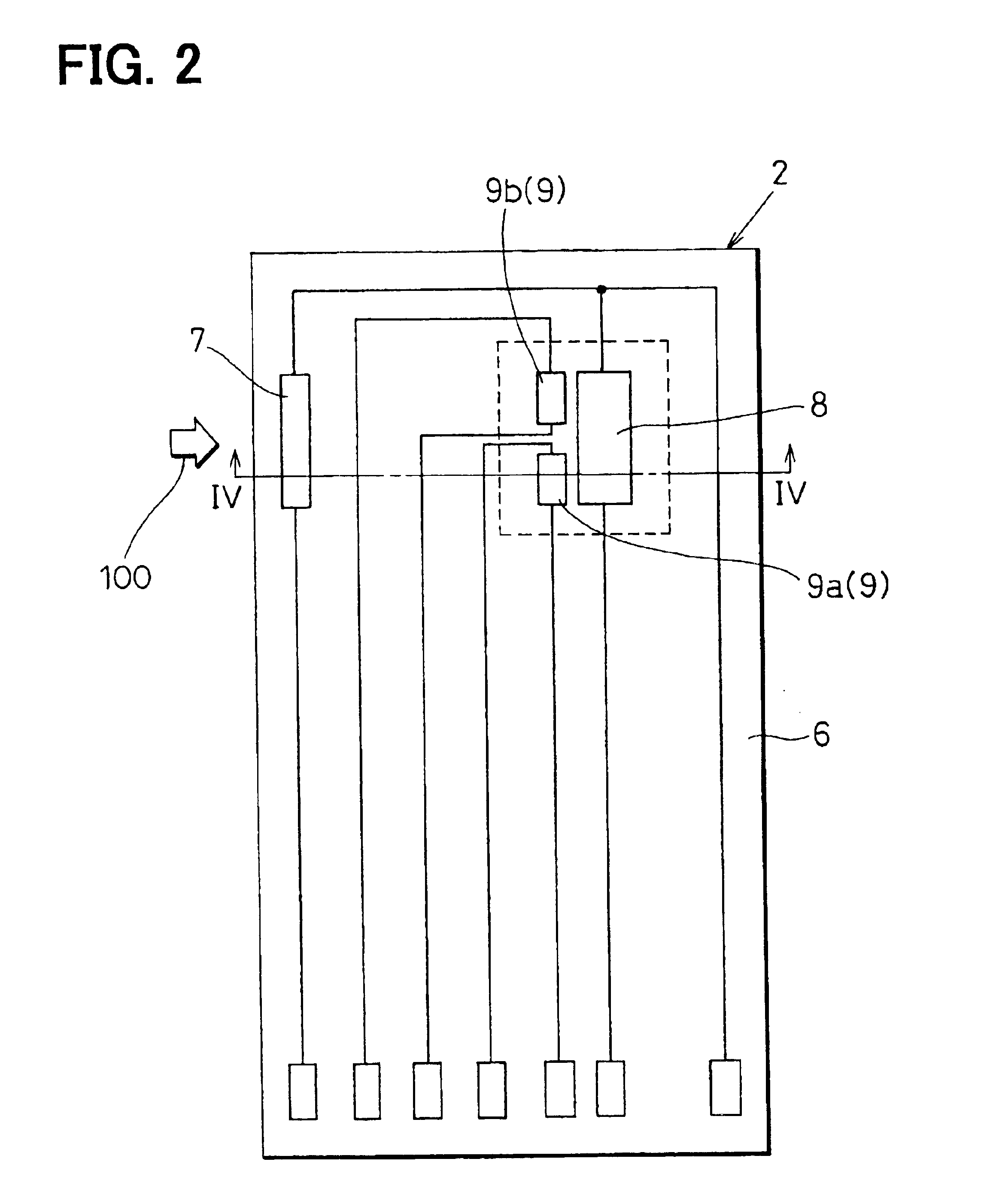
As shown in FIG. 2, the sensor 2 is ...

second embodiment

FIG. 9 and FIG. 10 shows a second embodiment of the present invention. In this embodiment, an output circuit 61 is utilized. The output circuit 61 uses resistors 21, 22 of which resistance varies in response to the intake air temperature instead of the resistors 19, 20 in the first embodiment. The first and second resistors 9a, 9b are influenced by not only heat of the heating resistor 8 but also the intake air temperature. Therefore, it is possible to compensate shift of the temperature characteristic by using two resistors 21, 22 of which resistance varies in accordance with the intake air temperature in the bridge circuit. As a result, it is possible to achieve a stable output even if the intake air temperature was changed. Two resistors 21, 22 are formed on the same substrate 6 on which the resistor 7, the heating resistor 8 and the resistor 9 are formed as shown in FIG. 10. According to the arrangement, it is possible to reduce variation of resistance.

third embodiment

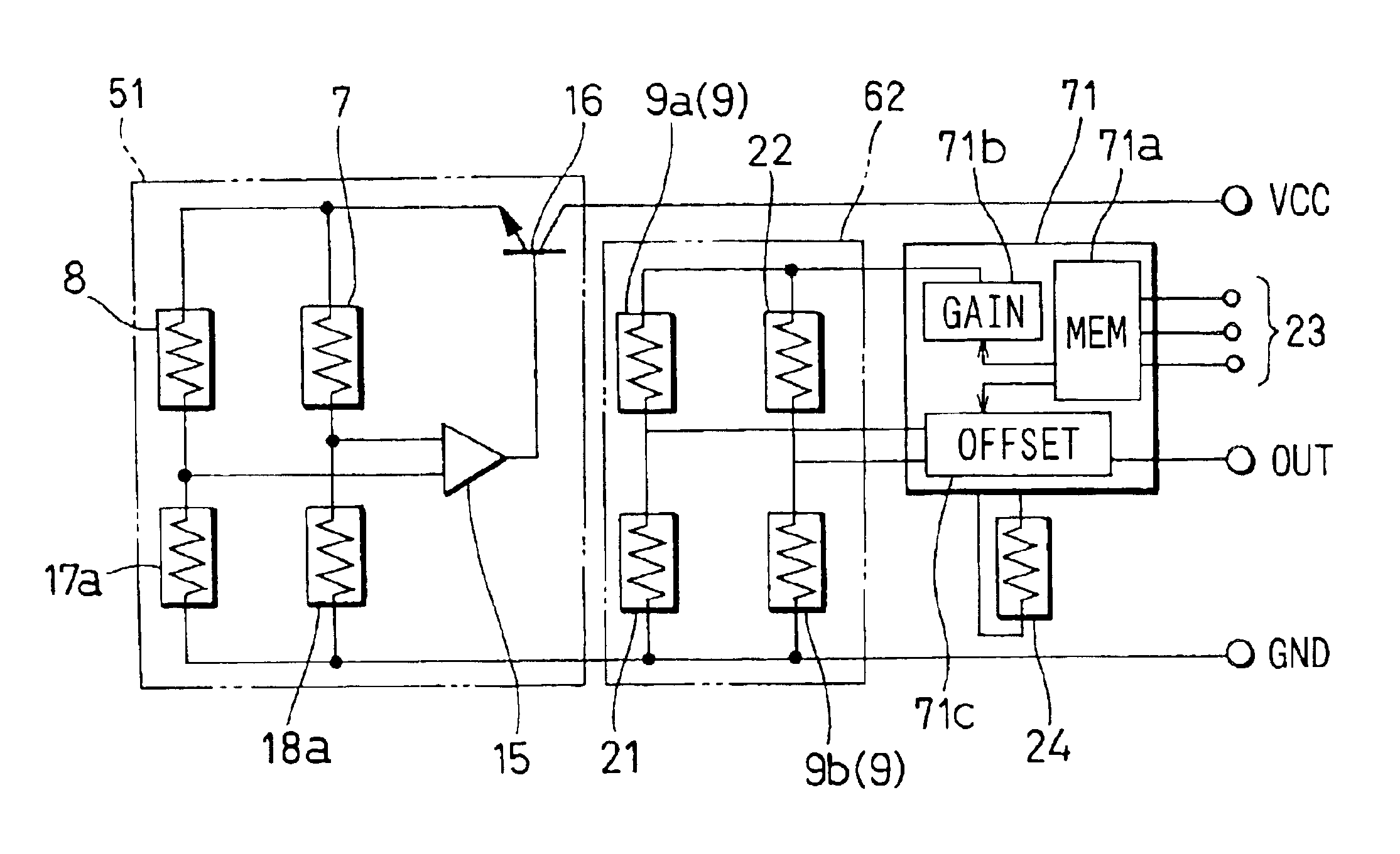
FIG. 11 and FIG. 12 show a third embodiment of the present invention. In this embodiment, a heater control circuit 51 is utilized. In the heater control circuit 51, resistors 17a, 18a are used instead of the resistors 17, 18 in the first embodiment. The resistors 17a, 18a are formed on the substrate 6. The resistors 17a, 18a are located on a place where an influence of the intake air temperature is hardly reached. The resistor 17a, 18a may be covered so as to not contact with the intake air. The first and second resistors 17a, 18a are formed on the same substrate 6 together with the resistor 7 and the heating resistor 8. Therefore, it is possible to reduce variation of resistance as small as possible. As a result, it is not needed to adjust resistance variation of each product. For example, it is possible to eliminate circuit adjusting process and resistance adjusting process by means such as the laser trimming.


PUM


Abstract

The flow amount measuring apparatus has two detecting portions for generating signal indicative of flow amount respectively. The outputs of two detecting portions are subject to a differential amplification to obtain large output signal and low amplitude ratio. A plurality of resistors providing the detecting portion may be formed on a single substrate. The output characteristic of the flow amount measuring apparatus can be adjusted by adjusting the gain and the offset. The offset includes a temperature dependent first offset component and a constant second offset component. The first offset component varies in accordance with temperature of fluid so as to reduce temperature dependency of the output characteristic. As a result, it is possible to measure flow amount accurately.

Description

CROSS REFERENCE TO RELATED APPLICATIONSThis application is based on Japanese Patent Applications No. 2002-41425 filed on Feb. 19, 2002 and No. 2003-10165 filed on Jan. 17, 2003 the contents of which are incorporated herein by reference.BACKGROUND OF THE INVENTION1. Field of the InventionThe present invention relates to a flow amount measuring apparatus for measuring flow amount of fluid.2. Description of Related ArtJP-A-2000-193505 discloses a flow amount measuring apparatus. The flow amount measuring apparatus has a temperature sensitive resistor that is disposed upstream a heating resistor. The temperature of the temperature sensitive resistor varies in accordance with flow amount of fluid and flow direction of fluid, and the temperature can be detected as resistance thereof. Therefore, the temperature sensitive resistor can detect both the flow amount of fluid and the flow direction of fluid.According to this technique, the temperature of the temperature sensitive resistor varies...

Claims


Application Information

Patent Timeline
IPC IPC(8): G01F1/684G01F1/698G01F1/696G01F5/00G01F1/692
CPCG01F1/6845G01F5/00G01F1/698
Inventor KOUNO, YASUSHI
Owner DENSO CORP
Learn More