Connection device and associated process

a technology of connection device and associated process, which is applied in the direction of coils, electromagnets, cores/yokes, etc., can solve the problems of prolonging the service life of the device, and achieve the effects of shortening the electrical connection pathway, compact structure, and reducing the cost of materials for making electrical conta

Inactive Publication Date: 2005-01-11
CLAAS INDTECHN
View PDF21 Cites 6 Cited by
  • Summary
  • Abstract
  • Description
  • Claims
  • Application Information

AI Technical Summary

Benefits of technology

An advantage of the present invention includes the allowance of direct contact between the contact elements of the control unit in an end face region facing towards the functional element and the solenoid. In this manner, the device according to the present invention exhibits a compact structure. The cost for materials for making electrical contact can be considerably reduced. The basic idea of the invention is to provide as short an electrical connection pathway as possible. Due to the shortening of the electric connecting lead and the integration of the control unit into a shielded housing, unwanted interference on electric lines is largely prevented. By this means, electromagnetic compatibility can be substantially improved with the detrimental effects on the electrical conductivity of device for making electrical contact reduced. The effect of this is to prolong the service life of the device.
According to an alternative embodiment of the invention, a side wall of the functional element, e.g., hydraulic valve block, serves as the bearing surface for an end face of the control unit. The control unit is pushed onto a tubular frame projecting away from the side wall of the hydraulic valve block. Electrical contact is made between the corresponding contact elements of the solenoid and the hydraulic valve block. The solenoid is fixed mechanically on the side wall of the hydraulic valve block. Advantageously, the contact elements of the solenoid or of the hydraulic valve block serve not just for elect...

Problems solved by technology

The effect of this is to prol...

Method used


Image

  • Connection device and associated process
  • Connection device and associated process
  • Connection device and associated process

Examples


Embodiment Construction

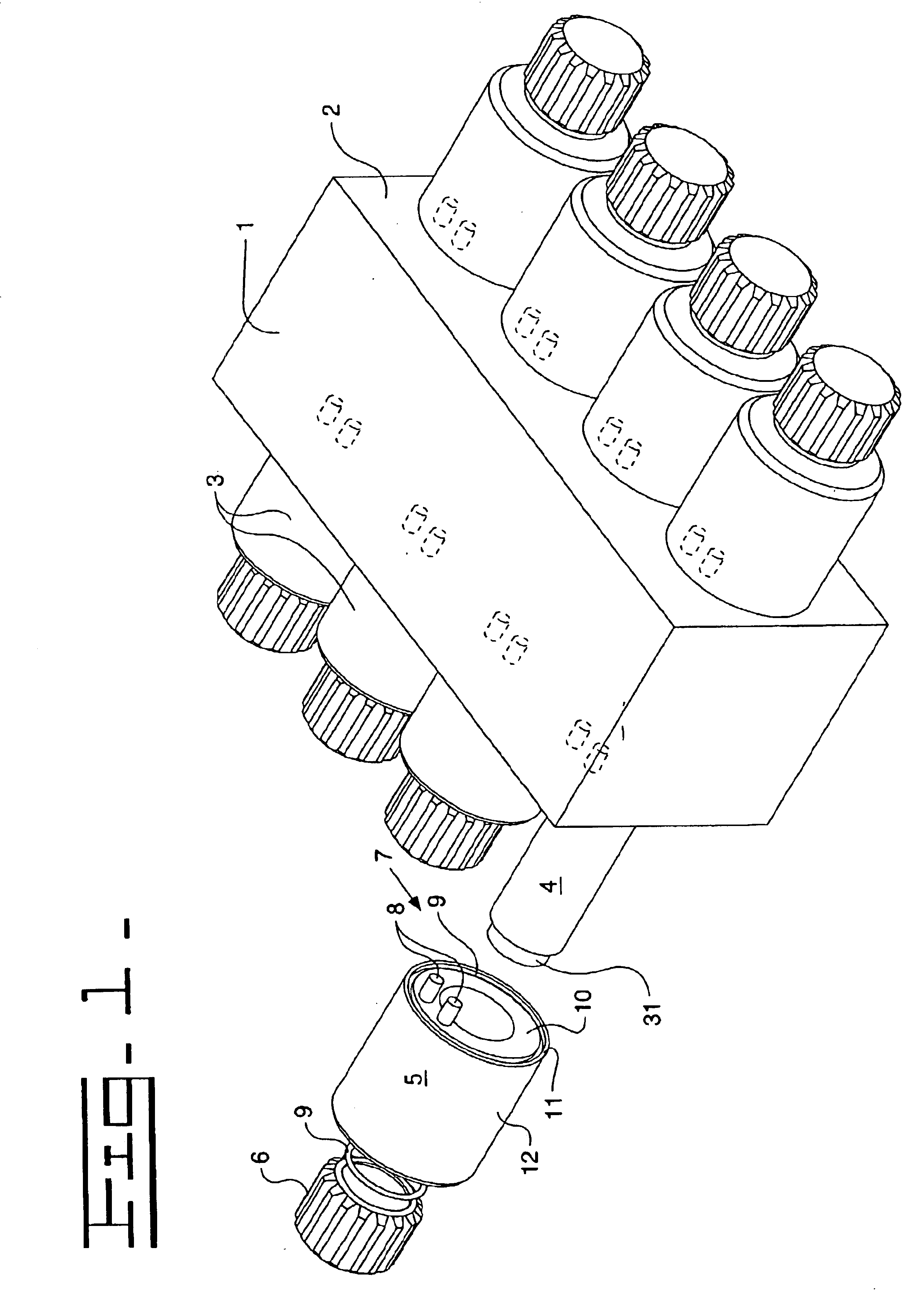
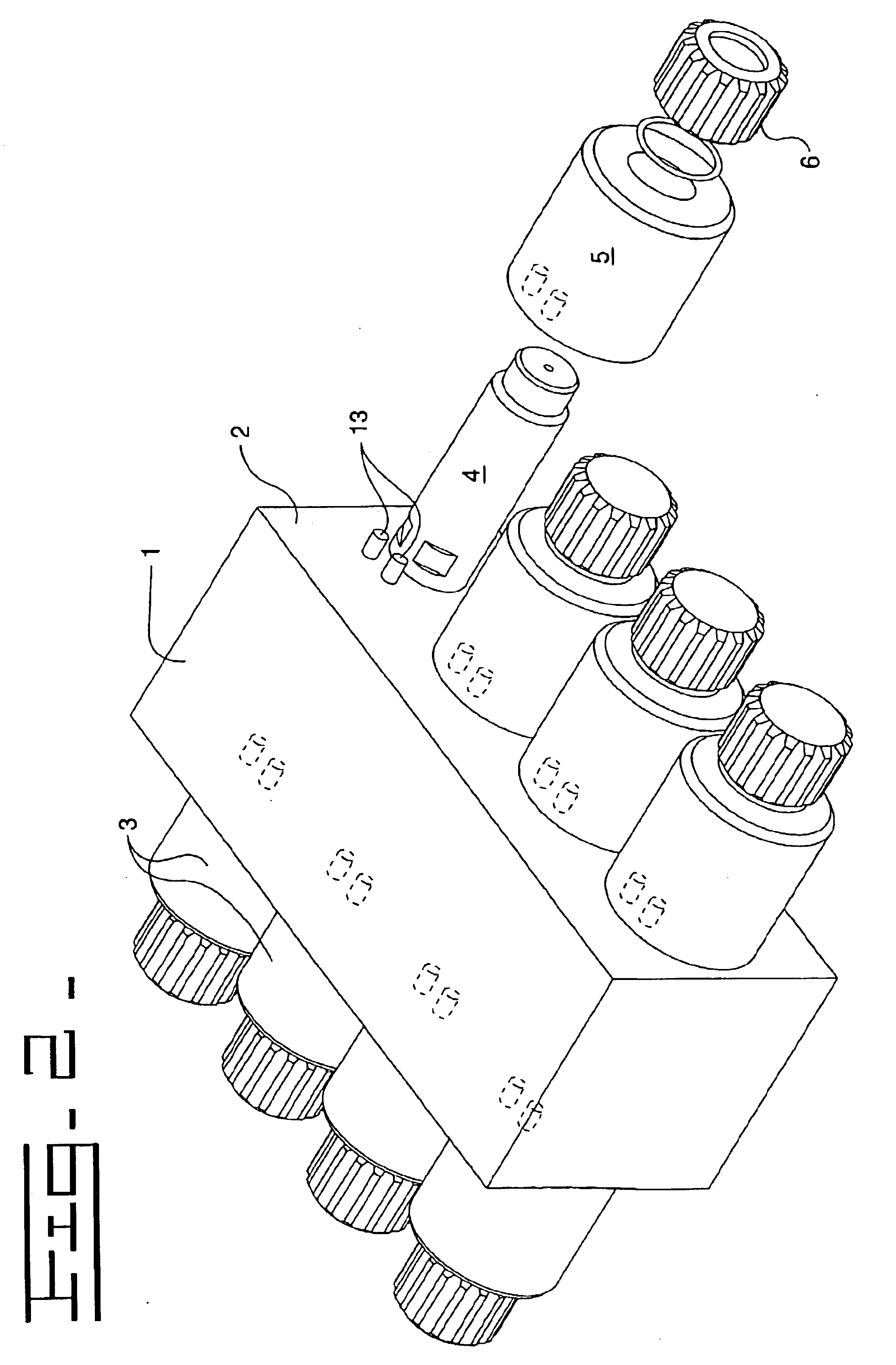
FIG. 1 shows a valve device that includes a housing 1 for a hydraulic valve block and solenoid valves 3 that are projecting away from side walls 2 of the valve block housing 1 and are preferably parallel to each other. The solenoid valves 3 are preferably arranged in rows with the two rows of opposite solenoid valves 3 lying in a common plane of extension. Although the geometric shape of the valve block housing 1 can vary tremendously, the preferred shape is that of a parallelepiped.

Contained in the valve block housing 1 are components which control the direction, the magnitude or the pressure of the volume flow of a liquid which is fed in and carried away through openings in the valve block housing 1, which are known to individuals with ordinary skill in the art and are not illustrated. The valve unit formed in this way can be employed, for example, as a directional control valve unit.

Actuation of this valve unit is accomplished through the solenoid valves 3, which are each formed ...


PUM


Abstract

The invention relates to a device for making contact between a solenoid and an electronic control unit arranged neighboring a valve block, wherein the solenoid projects away from a side wall of the valve block by a magnetic coil and a magnetic core, contact elements being arranged in an end face region of the solenoid facing towards the valve block in such a way that the contact elements can be directly electrically connected to corresponding contact elements arranged on a wall of the electronic control unit or of the valve block.

Description

BACKGROUND OF THE INVENTIONThe devices that are currently available for making contact between a control unit and the electrical connections of a functional element require a significant amount of structural space.For example, German Patent Application No. 198 48 039 A1 discloses a device for making contact between a solenoid valve and an electronic control unit that is assigned to a valve block. The solenoid valves for the control unit project away from a side wall of the valve block. Contact elements of a solenoid of the solenoid valve are arranged on a side of the solenoid valve facing away from the valve block and are connected to the electronic control unit via a connecting means. This arrangement of the electronic control unit is undesirable in devices where the solenoid valves each project away from a side wall of the valve block in opposite directions relative to one another.A brochure from BOSCH® about NG6 series D directional control valves, issue 2.0, discloses a device f...

Claims


Application Information

Patent Timeline
IPC IPC(8): B60T8/36F15B13/00H01F7/06H01F5/04H01F5/00F15B13/08
CPCB60T8/3675F15B13/0814F15B13/0828F15B13/0832F15B13/0875F15B13/0889H01F7/06F15B13/0857H01F2007/062H01F5/04Y10T137/87885Y10T137/5987
Inventor WOJCIECHOWSKI, THORSTEN
Owner CLAAS INDTECHN
Why Eureka
Try Eureka