Deformable brush seal support

a brush seal and support technology, applied in the direction of engine seals, leakage prevention, machines/engines, etc., can solve the problems of abradable material wear away instead of being axially displaced, leakage past the seal is no longer adequately controlled, etc., to prevent damage to the bristles

Inactive Publication Date: 2005-01-11
ANSALDO ENERGIA SWITZERLAND AG
View PDF12 Cites 33 Cited by
  • Summary
  • Abstract
  • Description
  • Claims
  • Application Information

AI Technical Summary

Benefits of technology

The present invention provides a brush seal for sealing between a rotating shaft and a housing, the brush seal comprising an annular head portion coaxial with the shaft and mounted on the housing, an annular array of bristles extending from the head portion toward the shaft for contact therewith at their end portions, and an annular support extending from the head portion toward the shaft and providing the array of bristles with support against axial deflection due to pressure differences across the seal, wherein the support includes a plurality of angularly spaced apart voids having radial and axial dimensions sufficient to allow the support to plastically deform preferentially in the radial direction by at least partial occlusion of the voids, and without significant plastic deformation in the axial direction, when there is rubbing contact between the support and the shaft.
The present invention is not designed to eliminate contact between the support and the shaft because it is desired to maintain an absolute minimum clearance between the support and the shaft as far as possible. The above-mentioned voids in the support enable radial plastic deformation of the support to occur preferentially, so allowing the support to shorten in the radial direction without any significant axial deformation. The voids are therefore at least partially filled by deformed material as the repeated contact between the support and the shaft effectively pushes the support in the radial direction. Substantial elimination of axial deformation of the support ensures that the seal between the bristles and the shaft is maintained and improves the cycle efficiency of the engine.
The shapes of the voids may be determined with reference to the heat dissipation characteristics of the support, to prevent damage to the bristles caused by a build up of heat from rubbing contact between the support and the shaft.
If the void is a radial channel or slot then the plurality of bristles are preferably angled in the circumferential direction with respect to a normal radius of the shaft, such that the bristles lie transversely of a major dimension of each void as manifested on a surface of the support. This prevents the channel or slot from interfering with the movement of the bristles. It also prevents the bristles from being received within the channel or slot where they could bend towards the low-pressure side of the brush seal.

Problems solved by technology

If the bristles 12 bend then the ends of some or all of the bristles may not continue to wipe against the surface of the shaft 2 and the leakage past the seal is no longer adequately controlled.
However, if the shaft 2 is subject to excessive radial movement in the vicinity of the brush seal then the bristles will be deflected and the shaft may come into repeated contact with the support 14.
If during operation of the brush seal the shaft contacts the base of the support then the abradable material will wear away instead of being axially displaced.

Method used


Image

  • Deformable brush seal support
  • Deformable brush seal support
  • Deformable brush seal support

Examples


Embodiment Construction

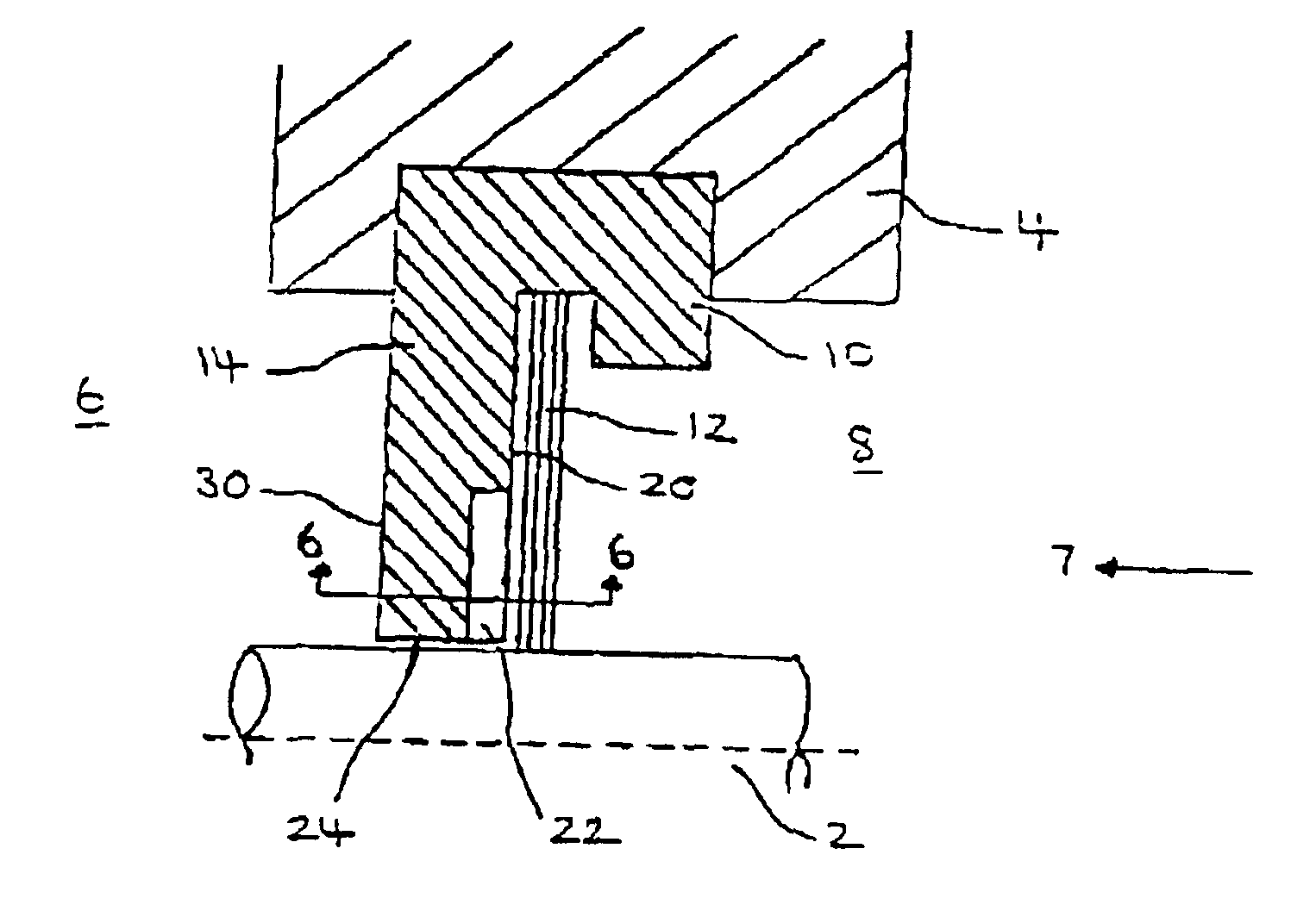
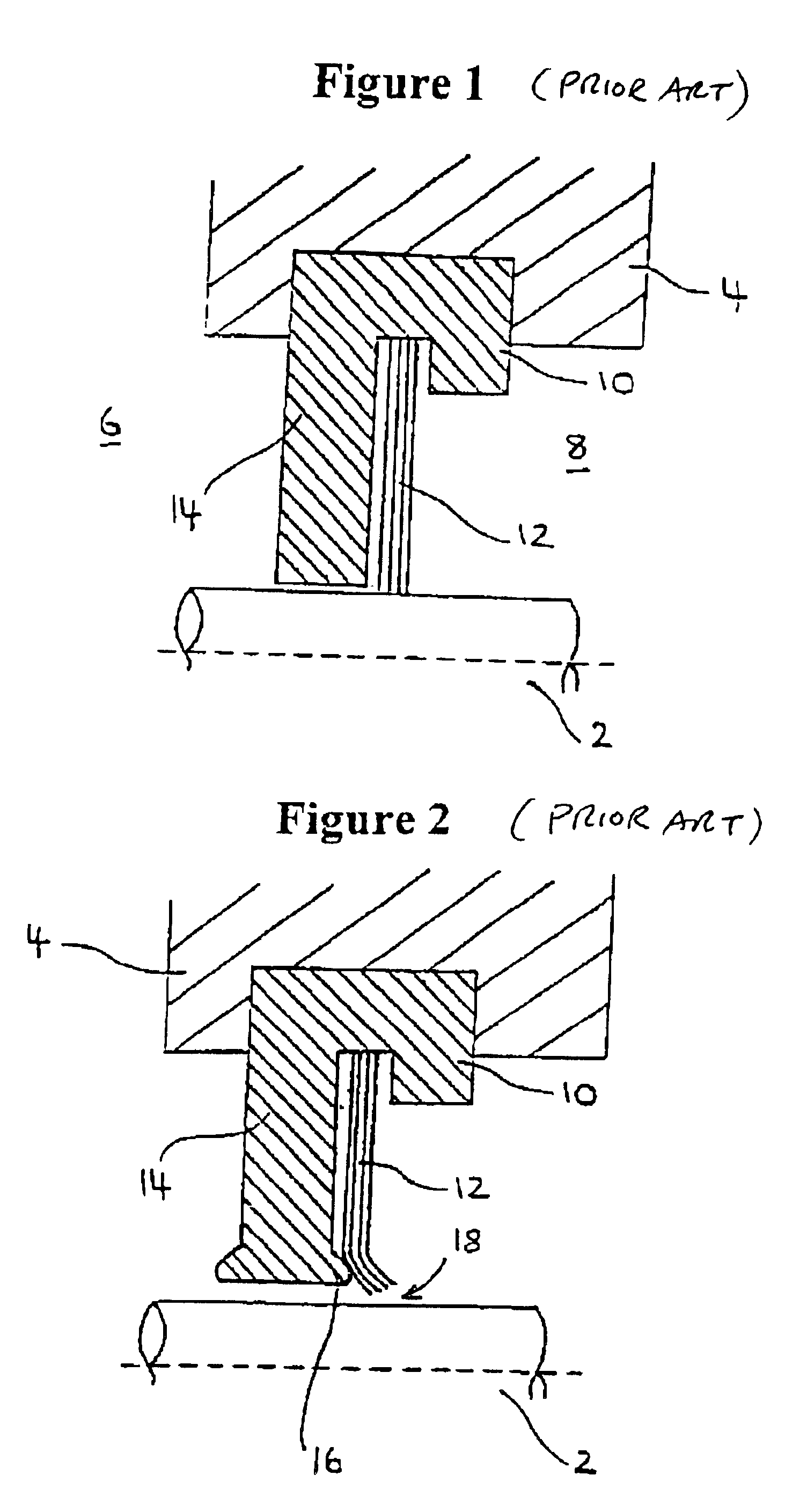
The present invention will now be explained with reference to FIGS. 3 to 7. The brush seal of FIG. 3 is similar to that of FIG. 1, and like parts have been given the same reference numerals.

In FIG. 3 the rear support 14 has an annular surface 20 adjacent the plurality of bristles 12. The support 14 includes an annular array of voids in the form channels 22 in the annular surface 20. These channels 22 extend radially from the radially inner surface 24 of the support 14 towards the head portion 10. The channels 22 are spaced circumferentially around the radially inner surface 24 of the support 14, as shown in FIGS. 6 and 7.

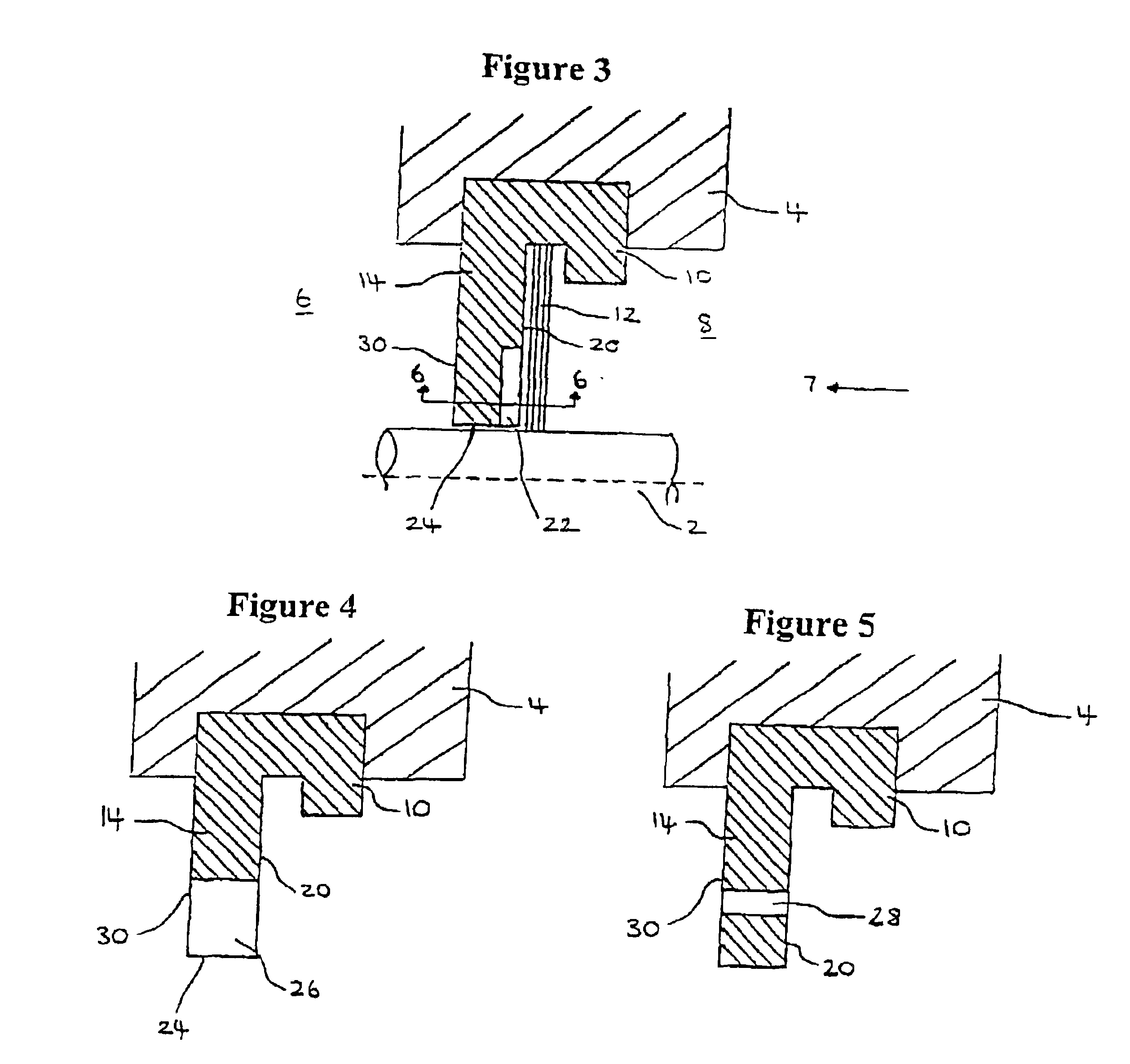
Alternative ways of implementing the voids in the supports are shown in FIGS. 4 and 5. In FIG. 4 a plurality of slots 26 extend radially from the support's radially inner surface 24 towards the head portion 10 and also extend radially from one annular surface 20 of the support 14 to the other annular surface 30. In FIG. 5 the support 14 includes a plurality of holes...


PUM


Abstract

A brush seal is provided for sealing between a rotating shaft and a housing. The brush seal includes an annular rim or head portion coaxial with the shaft and mounted on the housing, an annular array of bristles extending from the head portion toward the shaft for contact with the shaft at their ends, and an annular bristle support plate extending from the head portion toward the shaft. The support includes voids arranged to accommodate radial deformation in the support due to rubbing contact between the support and the shaft without incurring any substantial accompanying axial deformation which would distort the bristles and cause deterioration of their sealing function.

Description

BACKGROUND OF THE INVENTION1. Field of the InventionThe present invention relates to brush seals for dynamic shaft sealing, and in particular to brush seals having a deformable rear support.2. Description of the Related ArtThe background art will now be explained with reference to FIGS. 1 and 2. Brush seals are a common way of providing a seal to control leakage between a rotating shaft 2 and housing 4. They are typically found in gas turbine engines and the like, where they seal between a low-pressure region 6 of the engine and a high-pressure region 8. Brush seals usually include an annular rim or head portion 10 that is mounted on the housing 4 in such a way as to be coaxial with the shaft 2. The head portion 10 is usually formed from a high-grade stainless steel. A large number of bristles 12 extend from the head portion 10 towards the shaft 2 such that the ends of the bristles wipe against the surface of the shaft. The bristles 12 may comprise steels, nickel-based alloys or cer...

Claims


Application Information

Patent Timeline
Patent Type & Authority Patents(United States)
IPC IPC(8): F16J15/32
CPCF16J15/3288
Inventor BOSTON, IAN WILLIAM
Owner ANSALDO ENERGIA SWITZERLAND AG
Why Eureka
Try Eureka