This helps you quickly interpret patents by identifying the three key elements:
Problems solved by technology
Method used
Benefits of technology
Benefits of technology
The object of the present invention is to provide a type of limited slip differential characterized by larger fluctuating range in gear ratio and higher torque bias ratio, which can greatly improve the cross-country ability when one of the driving wheels is running on icy-snow road surfaces.
The principle of present invention is that the period of the gear ratio is increased to at least two pitches, thus in comparison to traditional design method, the number of the periods of the gear ratio fluctuation involved in one revolution of the pinion is reduced to one half or less, thus the speed ratio fluctuating range can be substantially increased while the relative angular acceleration between the pinion and side gears can be reduced at the same time.
The differential described in present patent is a type of fluctuating gear-ratio differential, the gear ratio fluctuates during the process of the engagement between the pinion and side gears, and the period of speed ratio fluctuation is increased to two pitches or higher, thus the speed ratio fluctuating range can be substantially increased while the relative angular acceleration between the pinions and side gears can be reduced at the same time.
For preferred embodiments, the present invention is a type of three-pitch fluctuating transmission-ratio differential, the gear ratio fluctuates during the process of the engagement between the pinion and side gears, and the period of speed ratio fluctuation is three pitches. Since the speed ratio fluctuation period is increased to three pitches, the relative angular acceleration between the pinions and side gears is greatly reduced, and the phenomenon of forming an edge on tooth surfaces will not happen even if the range of speed ratio between side gears is increased to 1:1.85. Because of the increment in speed ratio range, the height of potential barrier to the differential rotation is enhanced; meanwhile the range of the angle of rotation of the pinions corresponding to larger torque bias ratio is enlarged, the width of the potential barrier is also enlarged, which reduces the possibility of the pinions drive over the potential barrier caused by occasional vibration, and the reliability of anti-slip is improved. In this way, the torque bias ratio of the differential is substantially increased.
Problems solved by technology
Each model has some defects.
For inner friction model, which is the most widely used model of limited slip differentials, can be subdivided into preloaded and non-preloaded, both have the defects of higher price, and the later may be even more expansive, while the former may leads to a higher steering resistance and increased tire wear.
The overrunning model has complicated structure, works roughly, and some types have a lower reliability.
The electronic automatic differential locker also works roughly, being complicated in structure.
The limited-slip function realized by ABS system consumes more power.
The periodic change in the torque bias ratio forms two potential barriers, if the ratio of the torque acted on side gears does not reach the maximum torque bias ratio, the differential cannot make a continuous differential rotation, thus the slip of the driving wheel is limited.
Although the fluctuating range in gear ratio can be improved to a certain extent by means of optimization, the effect is limited.
Method used
Image
Click on the blue label to locate the original text in one second.
Reading with bidirectional positioning of images and text.
Examples
embodiment 1
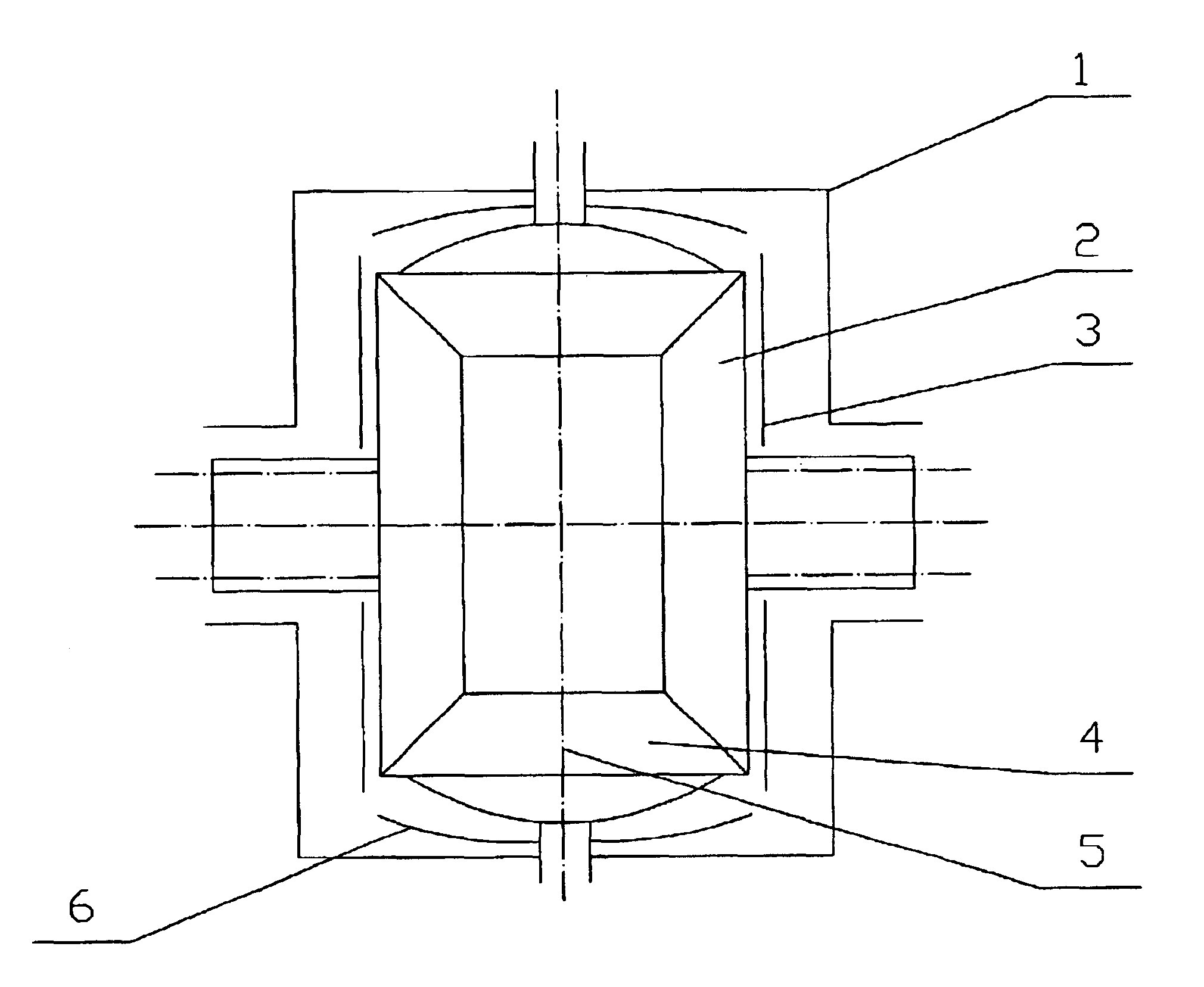
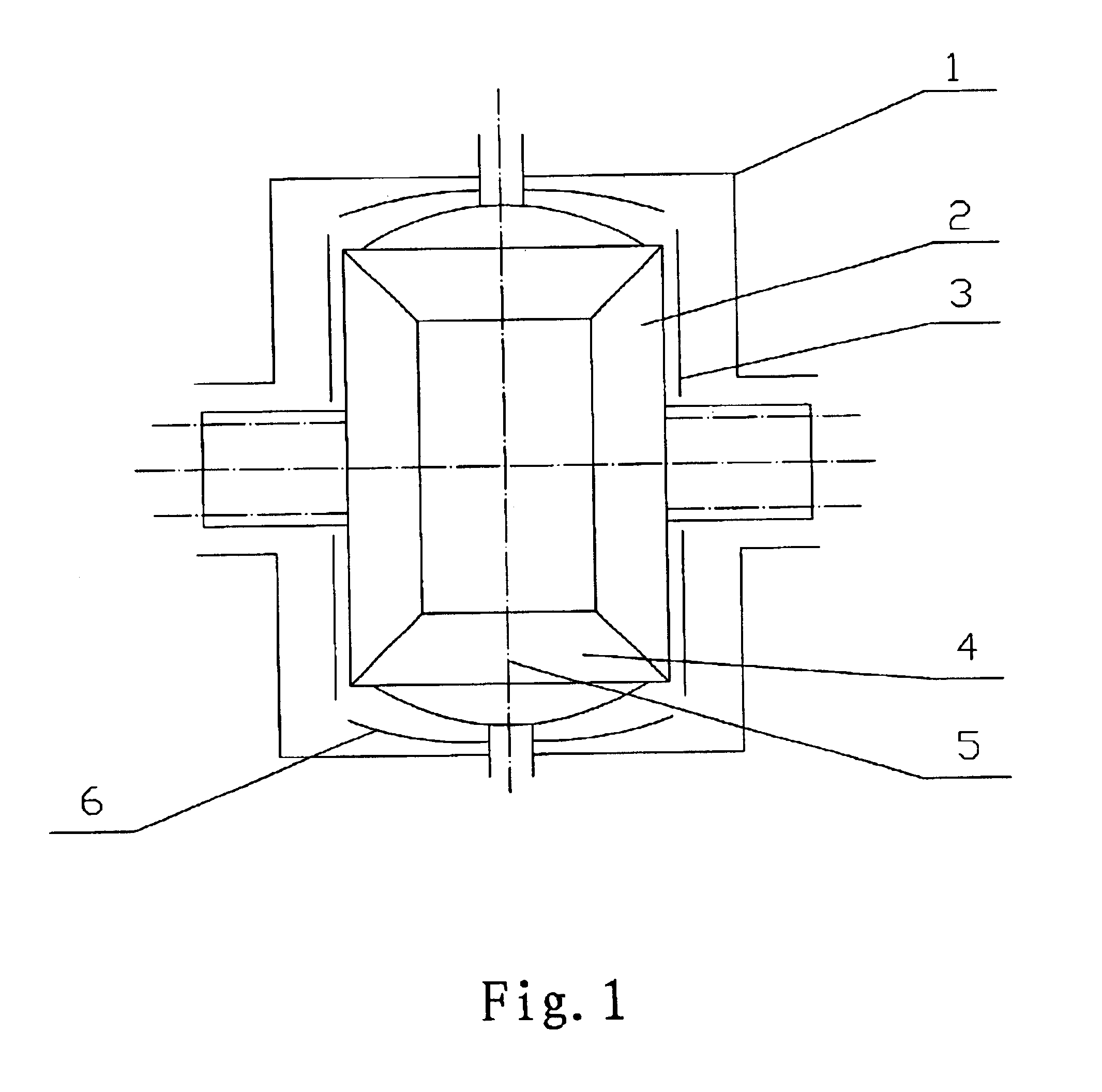
The structure of the embodiment is illustrated in FIGS. 1, 2 and 3. The fluctuating gear-ratio differential according to the present inventions involves a differential case 1, a pinion shaft 5, either a cross or straight shaft, fixed inside the differential case 1, the pinion gears 4 and a pair of
side gears 2, spherical thrust washers 6 situated between the back sides of the pinion gears 4 and the differential case 1, flat thrust washers 3 situated between the back sides of the side gears 2 and the differential case 1, said pinion gears 4 and side gears 2 compose plural gear pairs.
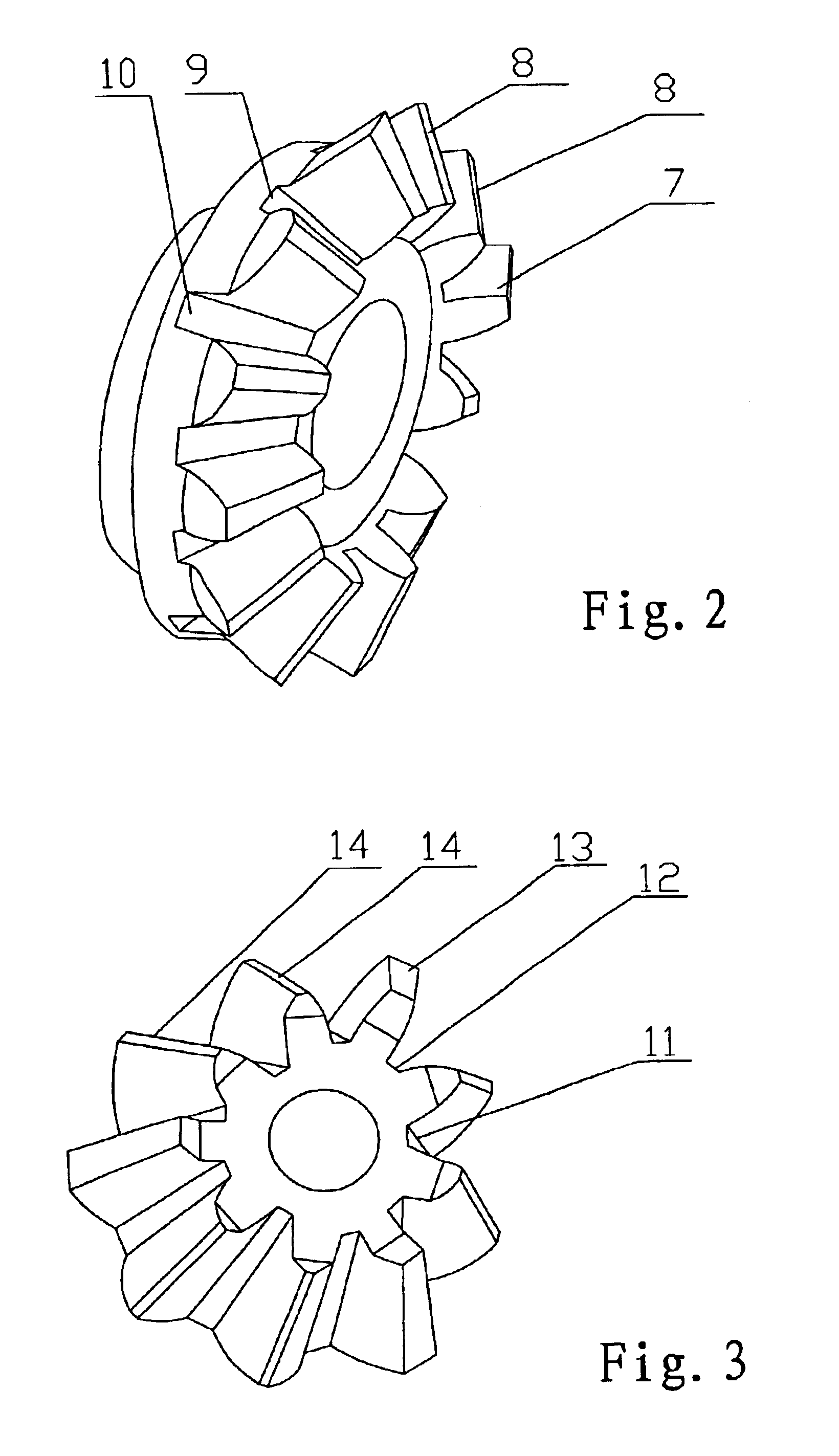
For Embodiment 1, the number of teeth in both pinion gears 4 and side gears 2 are chosen to be multiples of 3, during the engagement, the speed ratio fluctuates with a period of three pitches, thus in each period of the fluctuation in speed ratio, a group of three adjacent pairs of teeth are involved, each of them has individual profile. Within a group of three teeth, each one has its individual working ra...
embodiment 2
FIGS. 1, 4 and 5 illustrate Embodiment 2 in accordance with the present invention.
The structure, working principle and result of this embodiment are just the same to those of Embodiment 1, being not described here again.
The structure of the embodiment is illustrated in FIGS. 1, 4 and 5. The fluctuating gear-ratio differential according to the present inventions involves a differential case 1, a pinion shaft 5, either a cross or straight shaft, fixed inside the differential case 1, the pinion gears 4 and a pair of side gears 2, spherical thrust washers 6 situated between the back sides of the pinion gears 4 and the differential case 1, flat thrust washers 3 situated between the back sides of the side gears 2 and the differential case 1, said pinion gears 4 and side gears 2 compose plural gear pairs.
For Embodiment 2, the number of teeth in both pinion gears 4 and side gears 2 are chosen to be multiples of 3, during the engagement, the speed ratio fluctuates with a period of three pitc...
PUM
Abstract
A differential features larger amplitude in gear ratio fluctuation and higher torque bias ratio. When one of the driving wheel slips, the period of the gear ratio fluctuation between the pinion and side gears involves at least two pitches, thus each period of the gear ratio fluctuation involves a group of teeth, and the number of teeth involved in each group are corresponding to the number of pitches involved in each period. Each pinion has an odd number of groups of teeth, and the group number in side gears is a multiple of the number of pinions. The differential is particularly suitable for off-road vehicles, tippers and wheeled civil engineering machinery.
Description
BACKGROUND OF THE INVENTION1. Field of the InventionThis invention relates to limited-slip differentials for wheeled vehicles, particularly relates to a type of fluctuating gear-ratio limited-slip differential.2. Background of Related ArtLimited-slip differentials are well known and take different forms; the working principle can be divided into inner friction model, overrunning model, electronic controlled automatic differential locker, the limited slip function realized using ABS brakesystem, and potential barrier model. Each model has some defects.For inner friction model, which is the most widely used model of limited slip differentials, can be subdivided into preloaded and non-preloaded, both have the defects of higher price, and the later may be even more expansive, while the former may leads to a higher steering resistance and increased tire wear.The overrunning model has complicated structure, works roughly, and some types have a lower reliability.The electronic automatic d...
Claims
Application Information
Patent Timeline
Application Date:The date an application was filed.
Publication Date:The date a patent or application was officially published.
First Publication Date:The earliest publication date of a patent with the same application number.
Issue Date:Publication date of the patent grant document.
PCT Entry Date:The Entry date of PCT National Phase.
Estimated Expiry Date:The statutory expiry date of a patent right according to the Patent Law, and it is the longest term of protection that the patent right can achieve without the termination of the patent right due to other reasons(Term extension factor has been taken into account ).
Invalid Date:Actual expiry date is based on effective date or publication date of legal transaction data of invalid patent.

