High polymer electrolyte fuel cell and electrolyte film-gasket assembly for the fuel cell

a fuel cell and high-polymer technology, applied in the field of solid-phase electrolyte fuel cells, can solve the problems of gasket easily detachable from the electrolyte membrane, gas cross leakage, poor surface activity and no adhesiveness, etc., to achieve high pressure-proof seal, prevent gas leakage, and reduce manufacturing costs

Inactive Publication Date: 2005-01-11
PANASONIC CORP
View PDF14 Cites 89 Cited by
  • Summary
  • Abstract
  • Description
  • Claims
  • Application Information

AI Technical Summary

Benefits of technology

Moreover, by using the advantage of injection molding that can provide a molded product in any shape, the present invention prevents gas leakage due to hanging down of the gasket into the gas flow channels of the separator plates by providing the gasket with ribs and fitting the ribs into grooves formed in the separator plates. In other words, since the gasket is made of an elastic material, the ribs are fixed as being fitted into the separator plates by appropriate designs, thereby preventing the gasket from hanging down into the gas flow channels. By arranging the ribs to perform the function as walls that block gases cross leaking into the manifold apertures from the MEA, it is possible to achieve an extremely high pressure-proof seal as compared to a conventional example.
Furthermore, the present invention moves, to the gasket, part of the gas flow channels extending from the manifold apertures to the MEA and combines the gasket with MEA component members or separator plates produced by an inexpensive processing technique such as porous electrodes having gas flow channels or metal separator plates pressed into a wavy form in order to construct a gas flow channel mechanism of a cell. With this construction, it is possible to achieve a lowering of the manufacturing cost as well as an improvement in the volume output density.

Problems solved by technology

A serious problem in this type of fuel cells is gas cross leakage. FIG. 44 illustrates the structure in the vicinity of a manifold aperture for the oxidant gas in a fuel cell having the above-described structure.
This is a modified fluorocarbon resin membrane and has poor surface activity and no adhesiveness with respect to the gasket, and therefore the gasket easily detaches from the electrolyte membrane when the gasket deforms.
Consequently, when the fuel gas pressure is higher than the oxidant gas pressure, for example, the fuel gas leaks from the anode of a particular cell to the oxidant gas manifold aperture, thereby mixing with the oxidant gas.
In other words, gas cross leakage in one cell gives a considerable damage to the overall cell characteristics of the cell stack.
In the case of a cell stack, a significant increase in the number of parts is particularly unavoidable, resulting in a problem of very difficult assembly.
Moreover, the separator plate needs to be made thicker by an amount corresponding to the thickness of the bridge and that may cause considerable deterioration in the volume power density.
For this reason, it is difficult to implement the above-mentioned structure without increasing the overall thickness of the separator plate.
Furthermore, there is a problem of accuracy of processing the separator plates and the brides.
In an actual fact, however, it is hard to expect such a precise processing accuracy, and thus it is possible to reduce the amount of gas leakage but impossible to perfectly prevent the leakage.
A further problem is concerning the processing cost of the separator plates.
Since the machine work is a batch process, it has very poor mass productivity and takes enormous costs.
However, for fuel cells for use in vehicles, particularly, metal separator plates are advantageous because carbon that is a brittle material may be broken by vibration.
With some flat-surface gaskets, since the gas flow channels are closed, this technique is not available.
However, there was no other effective process that can give a three-dimensional structure to a conventional gasket for use in a polymer electrolyte fuel cell.

Method used


Image

  • High polymer electrolyte fuel cell and electrolyte film-gasket assembly for the fuel cell
  • High polymer electrolyte fuel cell and electrolyte film-gasket assembly for the fuel cell
  • High polymer electrolyte fuel cell and electrolyte film-gasket assembly for the fuel cell

Examples


embodiment 1

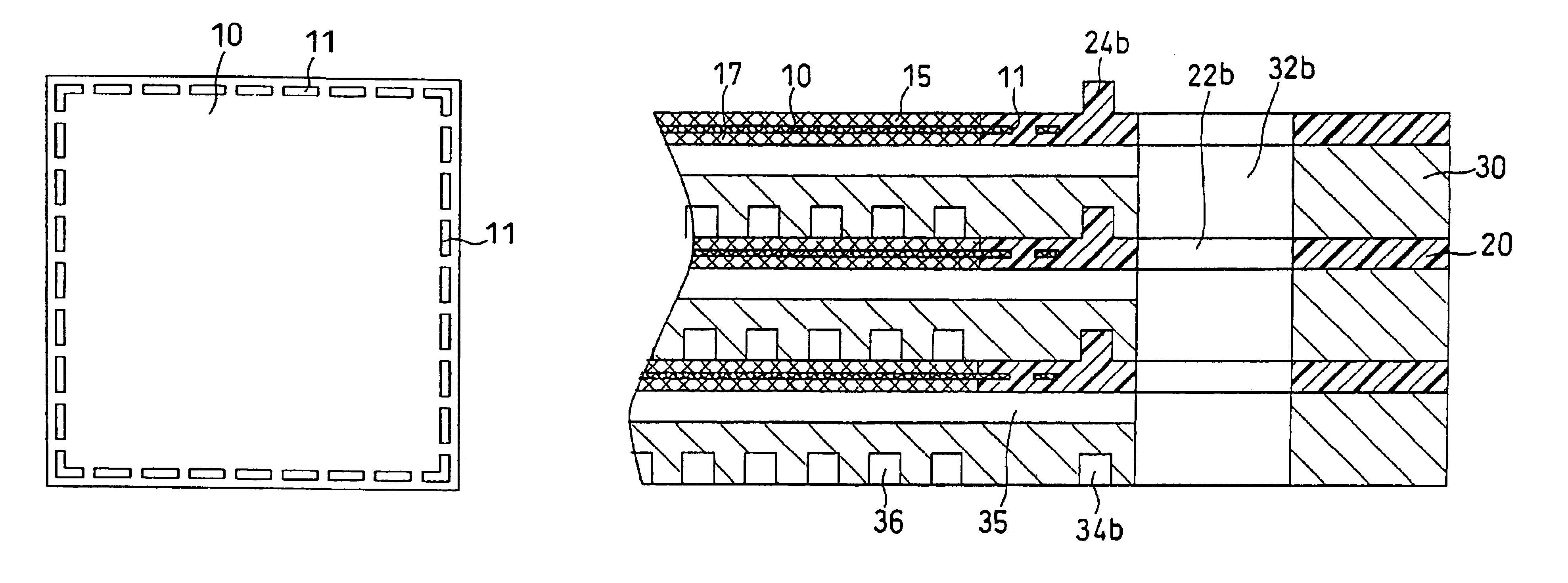
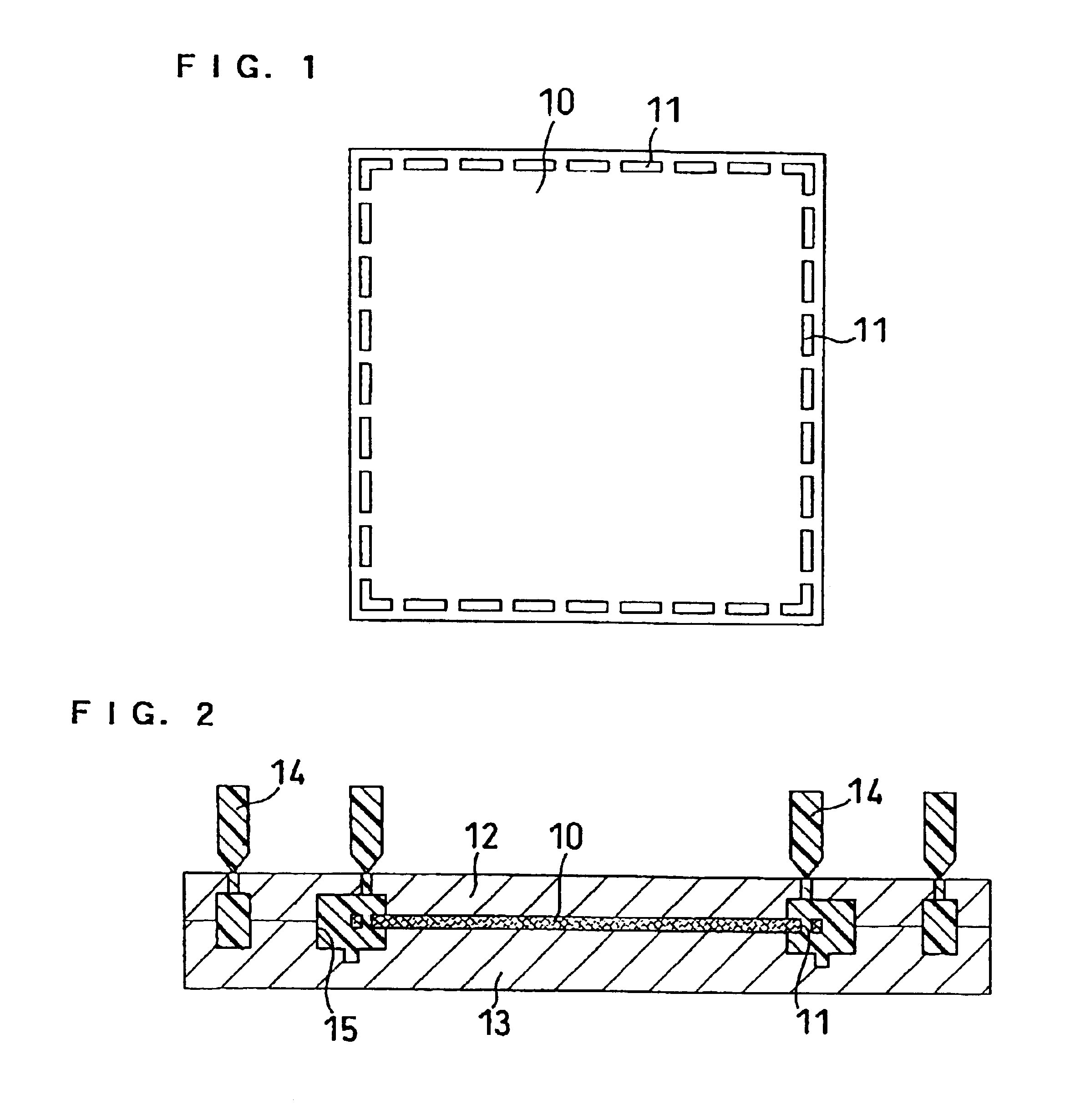
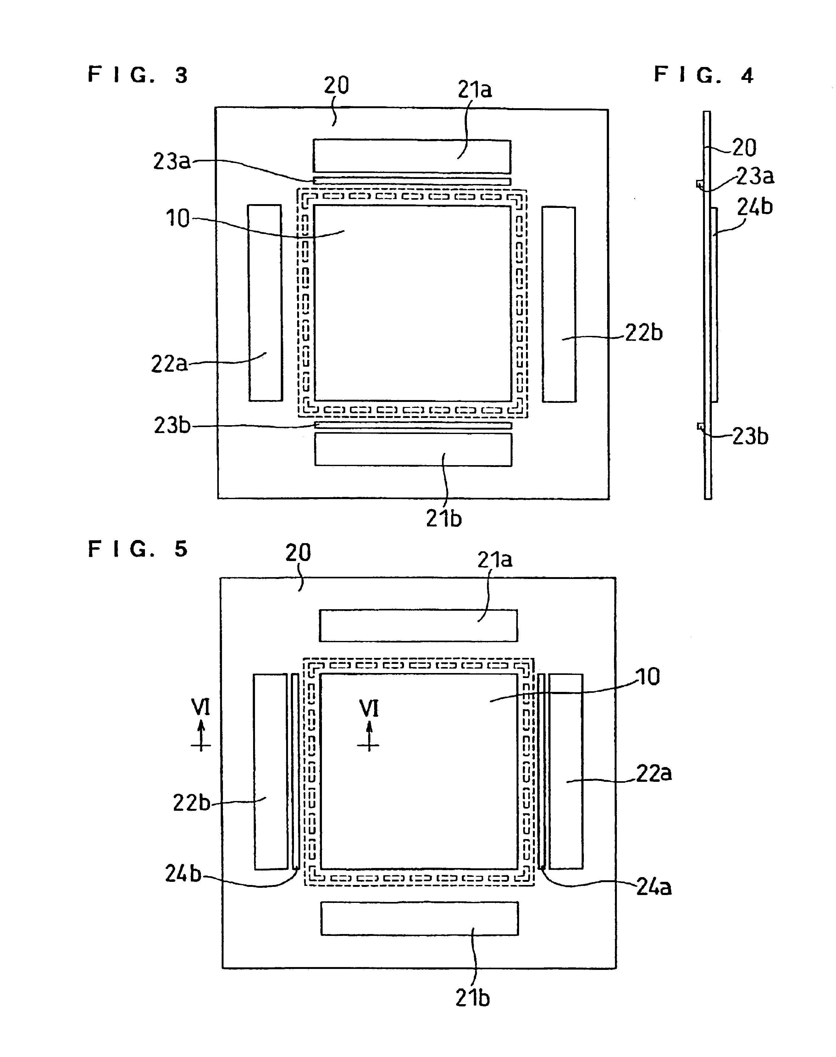
FIGS. 3 through 6 show an electrolyte membrane-gasket assembly according to this embodiment. This assembly comprises an electrolyte membrane 10, and a gasket 20 joined integrally to the peripheral portion of the electrolyte membrane 10 by injection molding. As illustrated in FIG. 1, formed in the peripheral portion of the electrolyte membrane 10 are a number of through-holes 11. This electrolyte membrane 10 is set in a mold composed of a cavity mold 12 and a core mold 13, and the frame-like gasket 20 is molded on the peripheral portion of the electrolyte membrane 10 by an insert injection molding process in which a melted thermoplastic resin or thermoplastic elastomer is poured into a molded product section 15 from gates 14.

The gasket 20 thus molded comprises a portion covering one surface of the electrolyte membrane 10 and a portion covering the other surface thereof, which are connected to each other through the regularly arranged through-holes 11 in the peripheral portion of the ...

embodiment 2

FIGS. 11 through 13 illustrate an electrolyte membrane-gasket assembly according to this embodiment. Like Embodiment 1, a gasket 40 joined integrally to the electrolyte membrane 10 has an inlet-side manifold aperture 41a and an outlet-side manifold aperture 41b for the fuel gas, and an inlet-side manifold aperture 42a and an outlet-side manifold aperture 42b for the oxidant gas. The gasket 40 further has, on a surface thereof facing the cathode-side conductive separator plate, gas flow channels 45a and 45b for connecting the cathode and the manifold apertures 42a and 42b, respectively, and, on a surface thereof facing the anode-side conductive separator plate, gas flow channels 46a and 46b for connecting the anode and the manifold apertures 41a and 41b, respectively.

FIGS. 14 and 15 show a cell structure using this electrolyte membrane-gasket assembly. An anode 55 has, on a surface thereof that does not face the electrolyte membrane, a gas flow channel 56 connected to the gas flow ch...

embodiment 3

FIGS. 18 through 20 illustrate an MEA of this embodiment, and FIGS. 21 through 23 show a conductive separator plate to be combined with this MEA. Like Embodiment 1, a gasket 60 is integrally joined to the peripheral portion of an electrolyte membrane 100 by injection molding. An anode 75 is joined to one surface of the electrolyte membrane 100 to which the gasket has been joined, while a cathode 77 is connected to the other surface thereof.

The gasket 60 has an inlet-side manifold aperture 61a and an outlet-side manifold apertures 61b for the fuel gas, an inlet-side manifold aperture 62a and an outlet-side manifold aperture 62b for the oxidant gas, and an inlet-side manifold aperture 63a and an outlet-side manifold aperture 63b for cooling water. The gasket 60 has, on the anode-side surface thereof, a rib 64 provided in the peripheral portion, and ribs 64a and 64b for separating the manifold apertures 62a, 63a and manifold apertures 62b, 63b from the anode 75. The rib 64 prevents the...


PUM

PropertyMeasurementUnit
thickaaaaaaaaaa
thicknessaaaaaaaaaa
thicknessaaaaaaaaaa

Abstract

An electrolyte membrane-gasket assembly for a fuel cell, including a polymer electrolyte membrane and a gasket, made of a seal material, covering the peripheral portion of the electrolyte membrane, in which the electrolyte membrane has a sequence of a plurality of through-holes in the peripheral portion, and a portion of the gasket covering one surface of the electrolyte membrane and a portion covering the other surface are connected to each other through the through-holes of the electrolyte membrane. This assembly provides a polymer electrolyte fuel cell free from gas cross leakage caused by a detachment of the gasket from the polymer electrolyte membrane. It is preferable to further include catalyst layers carried on both surfaces of the polymer electrolyte membrane, respectively, and protective films covering, respectively, sections spanning from the peripheral portion of each of the catalyst layers to the peripheral portion of the polymer electrolyte membrane.

Description

TECHNICAL FIELDThe present invention relates to a solid polymer electrolyte fuel cell, and more particularly relates to an improvement in an assembly comprising an electrolyte membrane and a gasket arranged on the peripheral portion of the electrolyte membrane.BACKGROUND ARTA fuel cell comprising a polymer electrolyte membrane generates electric power and heat simultaneously by electrochemically reacting a fuel gas containing hydrogen and an oxidant gas containing oxygen such as air. This fuel cell is basically composed of a polymer electrolyte membrane for selectively transporting hydrogen ions and a pair of electrodes formed on both surfaces of the polymer electrolyte membrane, i.e., an anode and a cathode. The electrode usually comprises a catalyst layer which is composed mainly of carbon particles carrying a platinum group metal catalyst and is formed on the surface of the polymer electrolyte membrane and a diffusion layer which has both gas permeability and electronic conductiv...

Claims


Application Information

Patent Timeline
Patent Type & Authority Patents(United States)
IPC IPC(8): H01M8/24H01M8/02H01M8/10
CPCH01M8/0273H01M8/241H01M8/242Y10T29/49115Y02E60/50Y10T29/49114Y10T29/4911H01M2008/1095H01M8/2483H01M8/0267H01M8/0263H01M8/02H01M8/04H01M8/0271
Inventor KOBAYASHI, SUSUMUHOSAKA, MASATOHATOH, KAZUHITOMURAKAMI, HIKARUTAKEZAWA, MIKIOONISHI, TAKAYUKI
Owner PANASONIC CORP
Why Eureka
Try Eureka