Spinner disc and method
- Summary
- Abstract
- Description
- Claims
- Application Information
AI Technical Summary
Benefits of technology
Problems solved by technology
Method used
Image

Examples
first embodiment
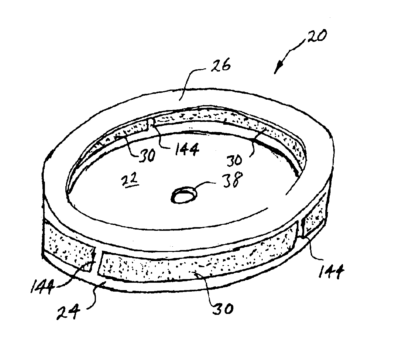
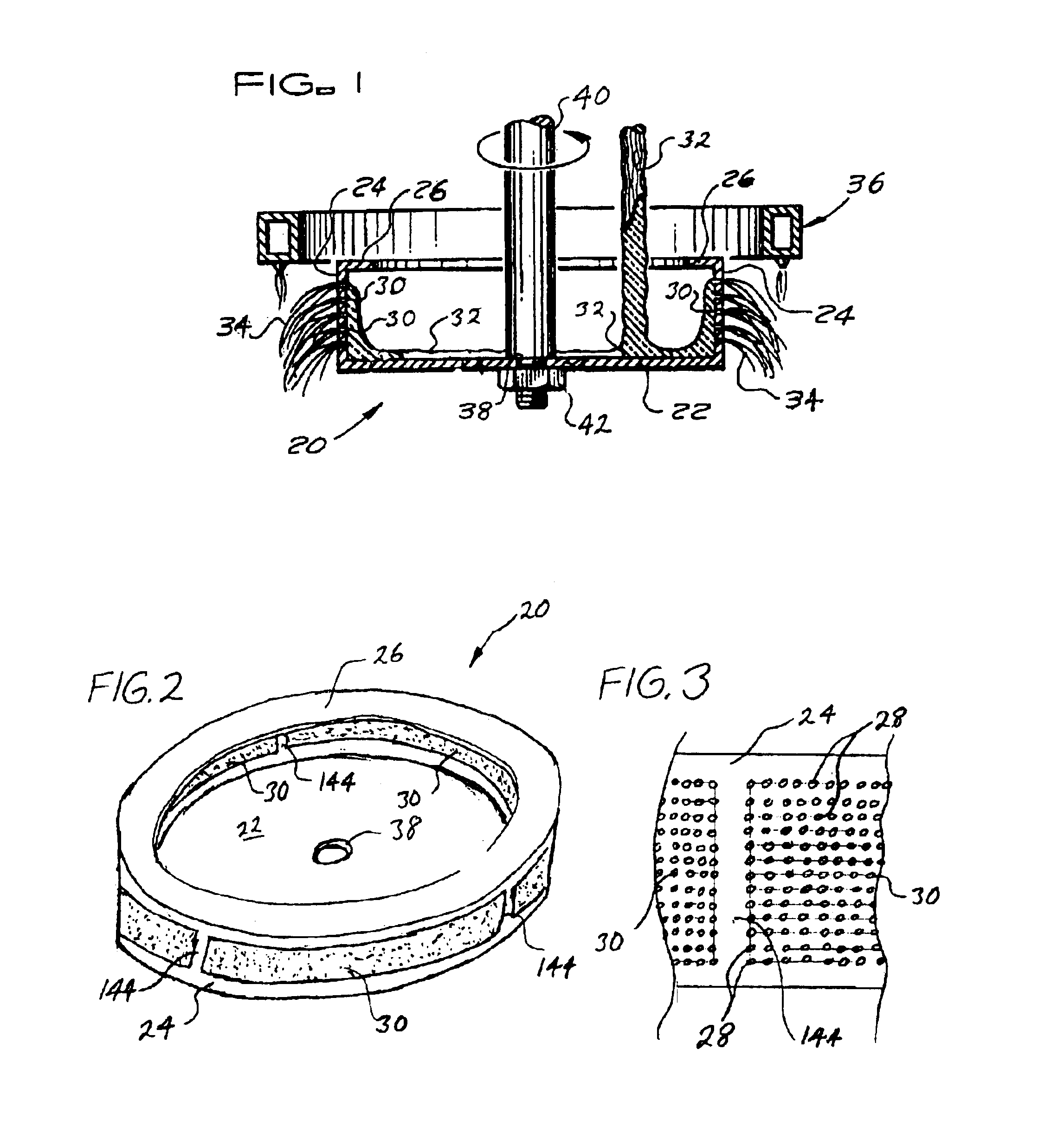
FIGS. 2 and 3 show the generally vertically extending holeless retaining bands that interrupt the rows 28 of fiberizing holes 30 in the sidewall 24 of the spinner disc 20. As shown in FIGS. 2 and 3, there are a plurality of generally vertically extending holeless retaining bands 144 for retaining the upper portion of the spinner disc 20, including the upper annular reinforcing flange 26, connected to the remainder of the spinner disc 20 when there is a rupture or other structural failure along one or more of the rows 28 of fiberizing holes 30 in the sidewall 24. The generally vertically extending holeless retaining bands 144 each extend completely through all of the rows 28 of fiberizing holes 30 including the uppermost row 28 and the lowermost row 28 of fiberizing holes 30.
second embodiment
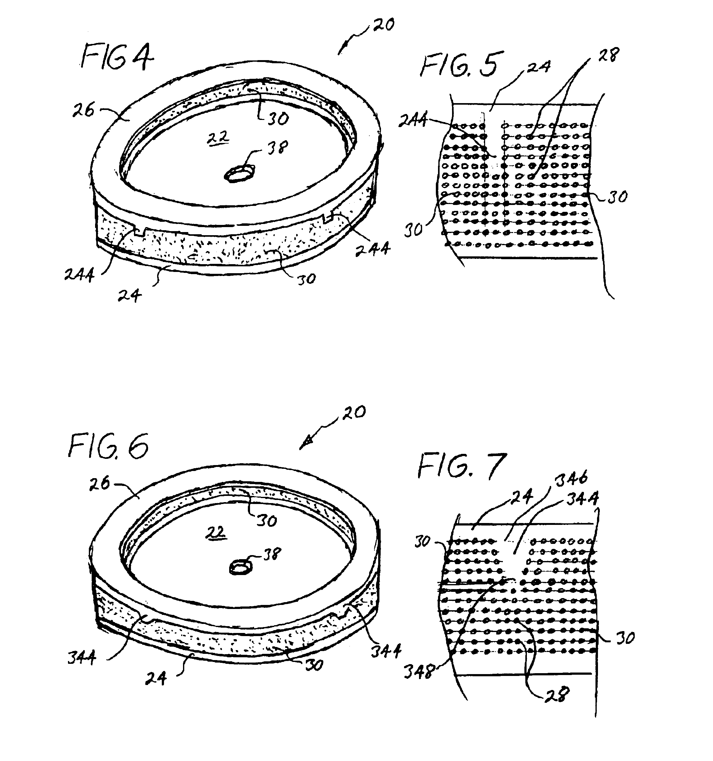
FIGS. 4 and 5 show the generally vertically extending holeless retaining bands that interrupt the rows 28 of fiberizing holes 30 in the sidewall 24 of the spinner disc 20. As shown in FIGS. 4 and 5, there are a plurality of generally vertically extending holeless retaining bands 244 for retaining the upper portion of the spinner disc 20, including the upper annular reinforcing flange 26, connected to the remainder of the spinner disc 20 when there is a rupture or other structural failure along one or more of the upper five rows 28 of fiberizing holes 30 in the sidewall 24. As shown, the generally vertically extending holeless retaining bands 244 each extend completely through the uppermost five rows 28 of fiberizing holes 30. While the generally vertically extending holeless retaining bands 244 are shown extending completely through the uppermost five rows 28 of fiberizing holes 30, the generally vertically extending holeless retaining bands 244 may be extended through more or less ...
PUM
 Abstract
Description
Claims
Application Information