Magnetic coupling using halbach type magnet array

a magnet array and magnetic coupling technology, applied in the direction of magnetic circuit rotating parts, magnetic circuit shape/form/construction, mechanical energy handling, etc., can solve the problems of difficult or undesirable to use conventional seals to seal the drive mechanism from the driving impeller, and achieve the effect of increasing the magnetic field strength, less leakage in the magnetic array, and maximizing the efficient transfer of magnetic flux

Inactive Publication Date: 2005-01-11
QUADRANT TECH CORP
View PDF16 Cites 181 Cited by
  • Summary
  • Abstract
  • Description
  • Claims
  • Application Information

AI Technical Summary

Benefits of technology

The present invention uses a conventional magnetic coupling arrangement such that north-pole and south-pole producing permanent magnets are angularly and alternately spaced about each of a pair of opposed annular arrays so as to generate a strong magnetic field adjacent to the pole faces of the magnets in the annular gap between the arrays to effect a coupling force across such gap. However, in contrast to the prior art structures for such coupling arrangements, a Halbach type of magnet array is provided whereby the adjacent north-pole and south-pole magnets in each array are connected by one or more spacer permanent magnets which are magnetized so as to provide a magnetic flux path annularly within the array between the north-pole, south-pole magnets rather than through a separate, magnetically conductive member externally of the magnet array. The north-pole, south-pole and spacer magnet arrangement should form a perfect annulus so that a uniform inner annular surface is provided at the annular space, or gap, adjacent to the north-pole, south-pole magnet faces and a uniform outer annular surface is provided at an annular location spaced from the gap. This innovation has resulted in less leakage in the magnetic arrays and a significant increase in the magnetic field strength at the gap for a given volume of magnetic array.
In the preferred arrangement, and in order to maximize the efficient transfer of magnetic flux within the magnetic array and minimize the flux leakage, the north-pole and south-pole magnets are tapered in the radial direction away from the gap so that a relatively large surface area of such magnets is presented at the gap and a relatively small surface area is presented at the outer annular surface of the array. Ideally, the annular surface of the north-pole and south-pole magnets at the outer annular surface of each array can be reduced to a minimum or knife-edge so that the north-pole and south-pole magnets are pie-shaped in general contour.

Problems solved by technology

Thus, they have been widely used on seal-less pumps, for example, wherein volatile, flammable, corrosive, abrasive, or foul-smelling liquids are being pumped and it is difficult or undesirable to use conventional seals to seal the drive mechanism from the driving impeller within the liquid.
Magnetic couplings have also found wide use in pumps or rotary positioning devices that are designed to operate in a vacuum wherein the provision of seals about a mechanical force-transmitting coupling would obviously create problems.

Method used


Image

  • Magnetic coupling using halbach type magnet array
  • Magnetic coupling using halbach type magnet array
  • Magnetic coupling using halbach type magnet array

Examples


Embodiment Construction

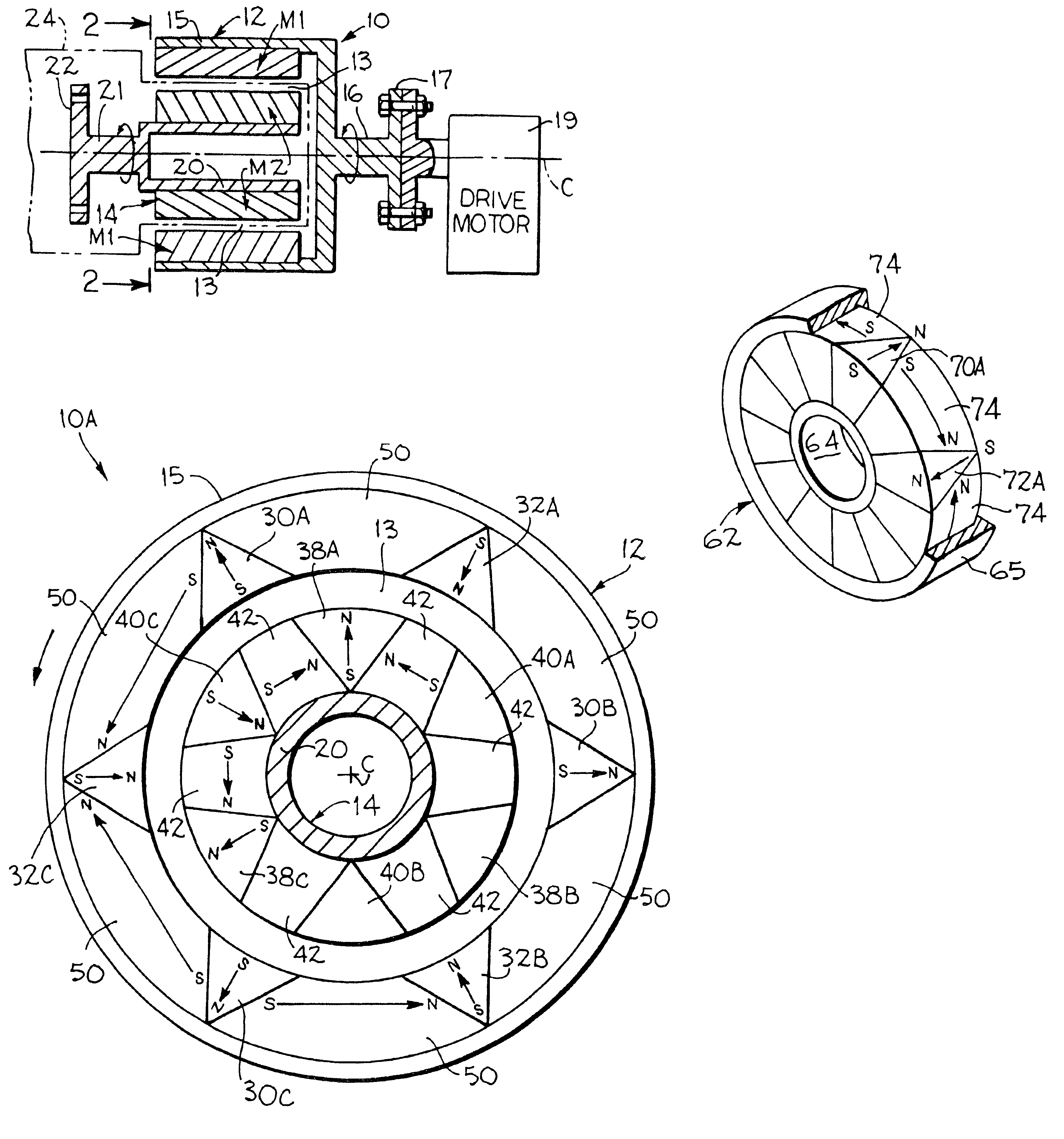
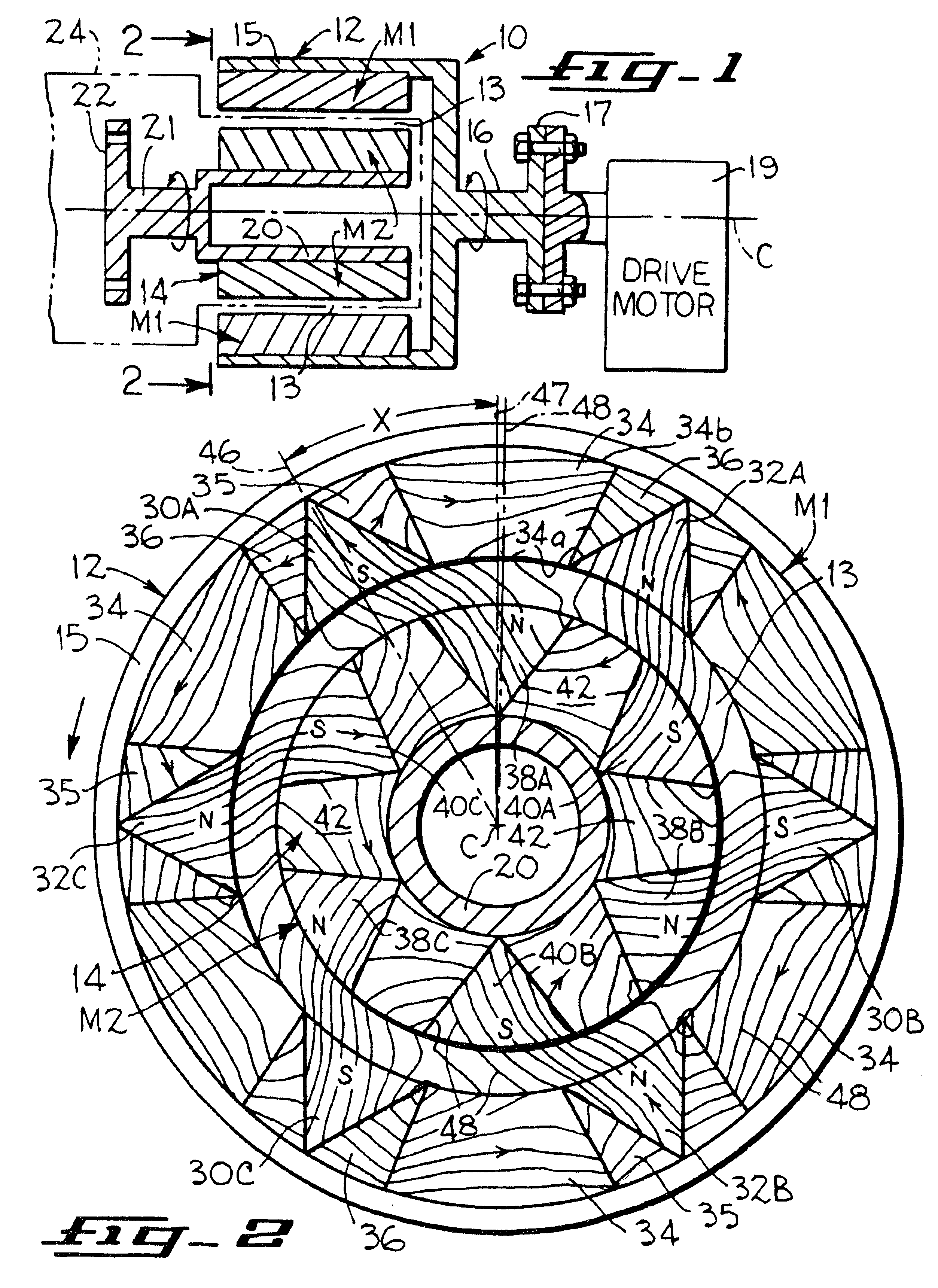
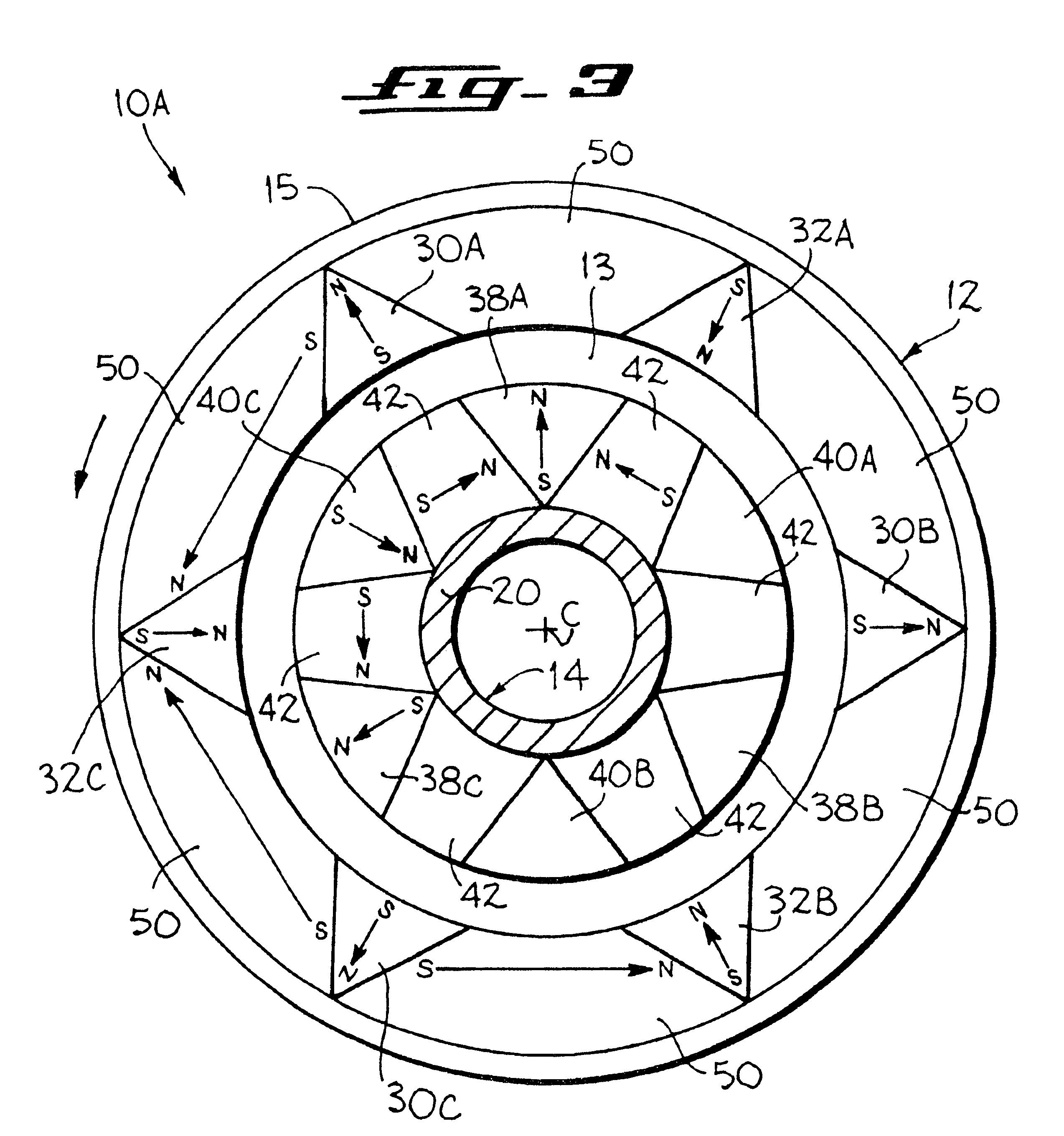
FIG. 1 illustrates in somewhat diagrammatic form one embodiment 10 of the magnetic coupling device of the present invention wherein a pair of opposed permanent magnet annular arrays 12, 14 are set in a concentric arrangement so as to provide an annular air gap 13 therebetween. The outer array 12 will be seen to include an inner permanent magnet annulus M1 comprised of a plurality of separately magnetized segments and an outer hub 15 having a thin annular wall of non-magnetic conductive material for securing the magnet annulus in place. The inner array 14 will be seen to include an outer permanent magnet annulus M2 comprised of a plurality of separately magnetized segments and an inner hub 20 having a thin annular wall of non-magnetic conductive material for securing the magnet annulus M2 in place.

While either the outer ring 12 or the inner ring 14 could equally well be used as the driving ring of the coupling (dependent only upon the particular end use to which the coupling is to be...


PUM


Abstract

A magnetic coupling having two opposed annular arrays of angularly spaced permanent magnets magnetized to create magnetic north poles and magnetic south poles alternately spaced about each array. The north-pole and south-pole magnets of each array are tapered in cross-section from their surfaces at the gap to an annular surface of the array spaced from the gap, and permanent magnet spacer magnets completely fill in the space between the north-pole and south-pole magnets from the annular surface of the array at the gap to the spaced annular surface with the spacer magnets being magnetized generally transversely to the direction of magnetization of the adjacent north-pole, south-pole magnets so that the magnetic field created by the permanent magnets extends across the gap and annularly through each array to cause one of the arrays to rotate in synchronism with the other array.

Description

BACKGROUND OF THE INVENTIONThe present invention pertains to magnetic couplings, and more particularly, it pertains to magnetic couplings comprised of annular arrays of angularly spaced permanent magnets sequentially polarized in opposite directions.Magnetic couplings are devices utilizing magnetic fields to transmit torque between a driving member and a driven member without any physical contact between the members. Thus, they have been widely used on seal-less pumps, for example, wherein volatile, flammable, corrosive, abrasive, or foul-smelling liquids are being pumped and it is difficult or undesirable to use conventional seals to seal the drive mechanism from the driving impeller within the liquid. Magnetic couplings have also found wide use in pumps or rotary positioning devices that are designed to operate in a vacuum wherein the provision of seals about a mechanical force-transmitting coupling would obviously create problems.Magnetic couplings typically include two annular a...

Claims


Application Information

Patent Timeline
Patent Type & Authority Patents(United States)
IPC IPC(8): H02K49/00H02K49/10
CPCH02K49/106
Inventor GERY, JEAN-MARC
Owner QUADRANT TECH CORP
Why Eureka
Try Eureka