LED lamp

a technology of led lamps and diodes, which is applied in the field of lightemitting diodes, can solve the problems of poor heatsink performance of led lamps, difficult miniaturization of packages, and worsening of led lamps, so as to improve the overall intensity of led lamps, improve heatsink performance, and improve the effect of luminous efficiency

Inactive Publication Date: 2005-01-11
PANASONIC SEMICON SOLUTIONS CO LTD
View PDF12 Cites 59 Cited by
  • Summary
  • Abstract
  • Description
  • Claims
  • Application Information

AI Technical Summary

Benefits of technology

Since the anode side of the red light-emitting element is higher in intensity than the cathode side of the same, the red light-emitting element is mounted while the anode side thereof is taken as an upper surface. As a result, the overall inten

Problems solved by technology

Further, there is needed a space for interconnecting the gold wires, thus posing difficulty in miniaturization of the package.
If an LED is miniaturized, the heatsinking performance of the LED wil

Method used


Image

  • LED lamp
  • LED lamp
  • LED lamp

Examples


first embodiment

A first embodiment of the invention will now be described by reference to FIGS. 1 and 2.

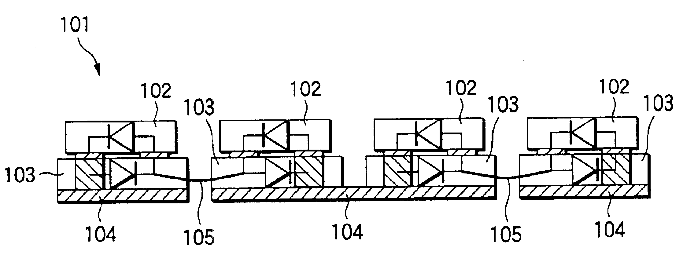
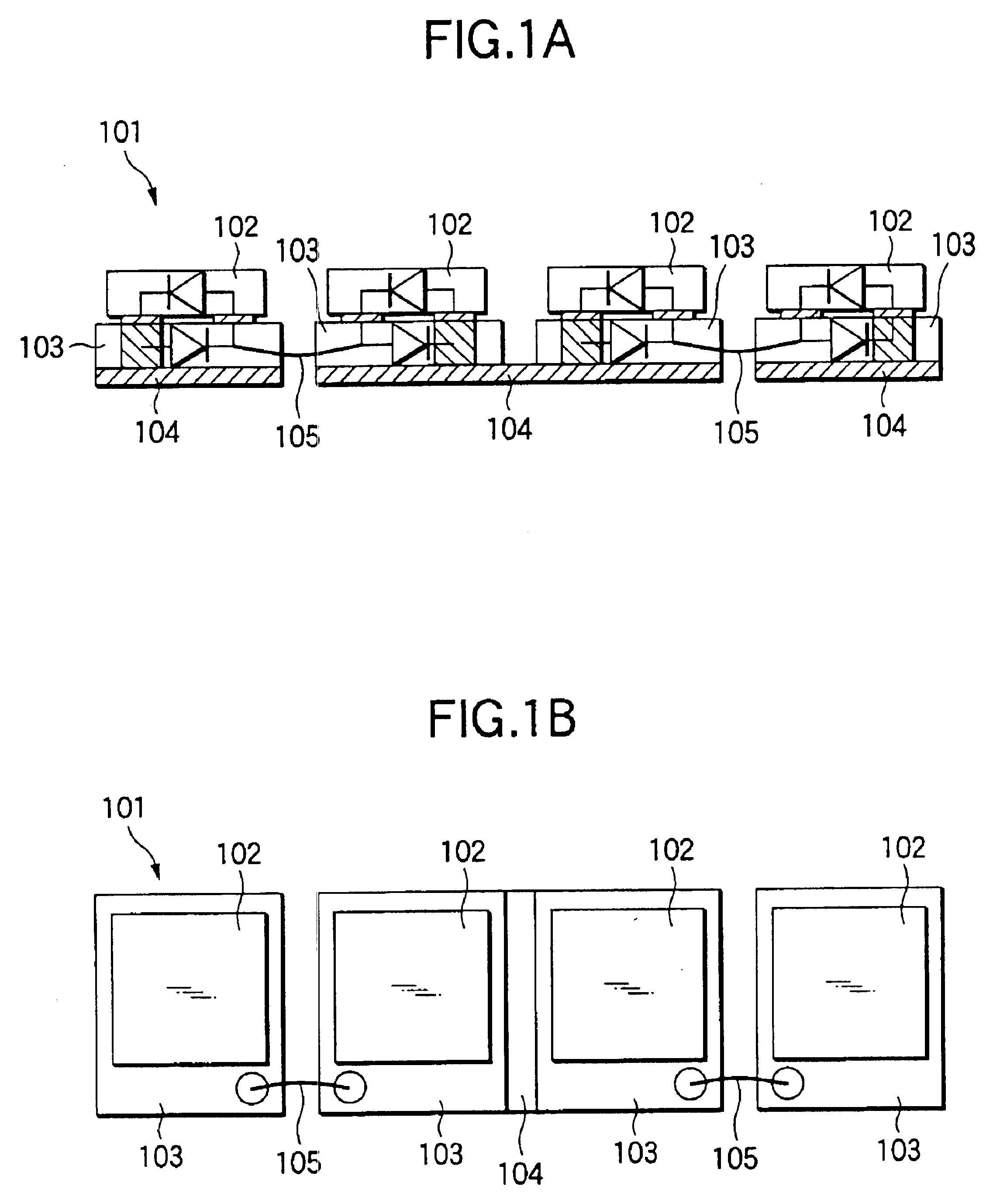
As shown in FIG. 1A, the circuit of the LED lamp 101 according to the first embodiment is constituted by means of connecting four GaN-based light-emitting elements 102 in series. Specifically, a Zener diode 103 is mounted on a copper plate 104, and a GaN-based light-emitting element 102 is mounted on the Zener diode 103 with an electrode of the element being oriented facedown. Here, adjacent Zener diodes 103 are reversed in polarity to each other. Further, two Zener diodes 103 close to the center of the LED lamp 101 are mounted on a common copper plate 104, thereby interconnecting the two light-emitting elements 102 in series. Consequently, a Zener diode 103 is connected to the respective two Zener diodes 103 by means of a wire 105 serving as a conductive member. Four light-emitting elements 102 are connected in series, so that four light-emitting elements 102 are connected in series, thus comple...

second embodiment

A second embodiment of the invention will now be described by reference to FIGS. 3A and 3B.

As shown in FIGS. 3A and 3B, in relation to an LED lamp 121 according to the second embodiment, seats 114a, 114b—which assume a two-way split concave reflector—are provided at upper ends of the two upright leads 116a, 116b. A Zener diode 113a is mounted on the bottom surface of the seat 114a, and a Zener diode 113b is mounted on the bottom surface of the seat 114b. The polarity of one of the Zener diodes 113a, 113b is reversed. The GaN-based blue light-emitting elements 112a, 112b are mounted on the Zener diodes 113a, 113 with their electrodes being oriented facedown. The wire 115 is bonded to the upper surfaces of the Zener diodes 113a, 113b, thereby interconnecting the light-emitting elements 112a, 112b in series. Upper portions of the leads 116a, 116b, the seats 114a, 114b, the Zener diodes 113a, 113b, the light-emitting elements 112a, 112b, and the wire 115 are sealed with transparent epox...

third embodiment

A third embodiment of the invention will now be described by reference to FIGS. 4A and 4B.

As shown in FIGS. 4A and 4B, in relation to an LED lamp 131 according to the third embodiment, a pair of plate-like leads 126a, 126b are sealed with transparent epoxy resin 127 serving as sealing material while extremities of the leads 126a, 126b are spaced apart from each other. Here, the transparent epoxy resin 127 maybe white heat-resistant resin which reflects light. In this case, the resin 127 has an effect of serving as a reflection case. When the optical radiation surface is embodied as a top surface of the reflection case, an efficiency of extracting light is greatly improved. At this time, a hole 124 is formed in the upper surface of the case such that the leads 126a, 126b become exposed. When the transparent epoxy resin 127 has become set, the pair of plate-like leads 126a, 126b are bent substantially at a right angle along the side surfaces of the transparent epoxy resin 127. The lea...


PUM


Abstract

In an LED lamp, a Zener diode is mounted on a copper plate, and a GaN-based light-emitting element is mounted on the Zener diode with an electrode of the element being oriented facedown. Two Zener diodes close to the center of the LED lamp are mounted on a common copper plate, thereby interconnecting the two light-emitting elements in series. Consequently, a Zener diode is connected to the respective two Zener diodes by means of a wire serving as a conductive member. Four light-emitting elements are connected in series, so that four light-emitting elements are connected in series, thus completing a circuit configuration. In this way, use of the Zener diodes for interconnection purpose enables a reduction in the number of minimum required wires. It is better to connect the wire to the upper surfaces of the Zener diodes, thereby obviating a necessity for a redundant wire space and enabling miniaturization of the LED lamp.

Description

The present application is based on Japanese Patent Applications No. 2001-113447 and 2001-194269, which are incorporated herein by reference.BACKGROUND OF THE INVENTION1. Field of the InventionThe present invention relates to a light-emitting diode lamp (hereinafter abbreviated as an “LED lamp”), wherein a plurality of light-emitting elements, a wiring sub-mount for electrically interconnecting the light-emitting elements, and a wire are housed in a case made of synthetic resin or the like and sealed with material, such as translucent, transparent epoxy resin. Throughout the specification, an LED chip itself is called a “light-emitting element,” and the entirety of a light-emitting device having a plurality of LED chips mounted thereon is called a “light-emitting diode lamp” or an “LED lamp.”2. Description of the Related ArtAt the time of designing of an LED-applied product, in terms of optics it is preferable to design an LED so as to become as much close to a point light source as...

Claims


Application Information

Patent Timeline
IPC IPC(8): H01L25/16H01L25/075
CPCH01L25/167H01L25/0753H01L2224/48465H01L2224/48247H01L2224/48097H01L2224/48137H01L2224/48091H01L2224/45144H01L2924/00014H01L2924/00H01L2224/48095
Inventor TAKAHASHI, YUJIKAGA, KOICHIKATO, HIDEAKIIKEDA, TADAAKIMIYAWAKI, MICHIO
Owner PANASONIC SEMICON SOLUTIONS CO LTD
Why Eureka
Try Eureka