Electron-multiplier and photo-multiplier having dynodes with partitioning parts

Inactive Publication Date: 2005-01-11
HAMAMATSU PHOTONICS KK
View PDF12 Cites 2 Cited by
  • Summary
  • Abstract
  • Description
  • Claims
  • Application Information

AI Technical Summary

Benefits of technology

In the photomultiplier according to the present invention, the surface area of the bonds between the dynodes and glass parts i

Problems solved by technology

However, since a glass layer is formed across the entire output end or input end surface of the metal plates (dynodes) in the photomultiplier described above, warping can occu

Method used


Image

  • Electron-multiplier and photo-multiplier having dynodes with partitioning parts
  • Electron-multiplier and photo-multiplier having dynodes with partitioning parts
  • Electron-multiplier and photo-multiplier having dynodes with partitioning parts

Examples


Embodiment Construction

An electron multiplier and photomultiplier according to a preferred embodiment of the present invention will be described in detail while referring to the accompanying drawings, wherein like parts and components are designated by the same reference numerals to avoid duplicating description. The preferred embodiment describes an example in which the present invention is applied to a photomultiplier used in a radiation detecting device.

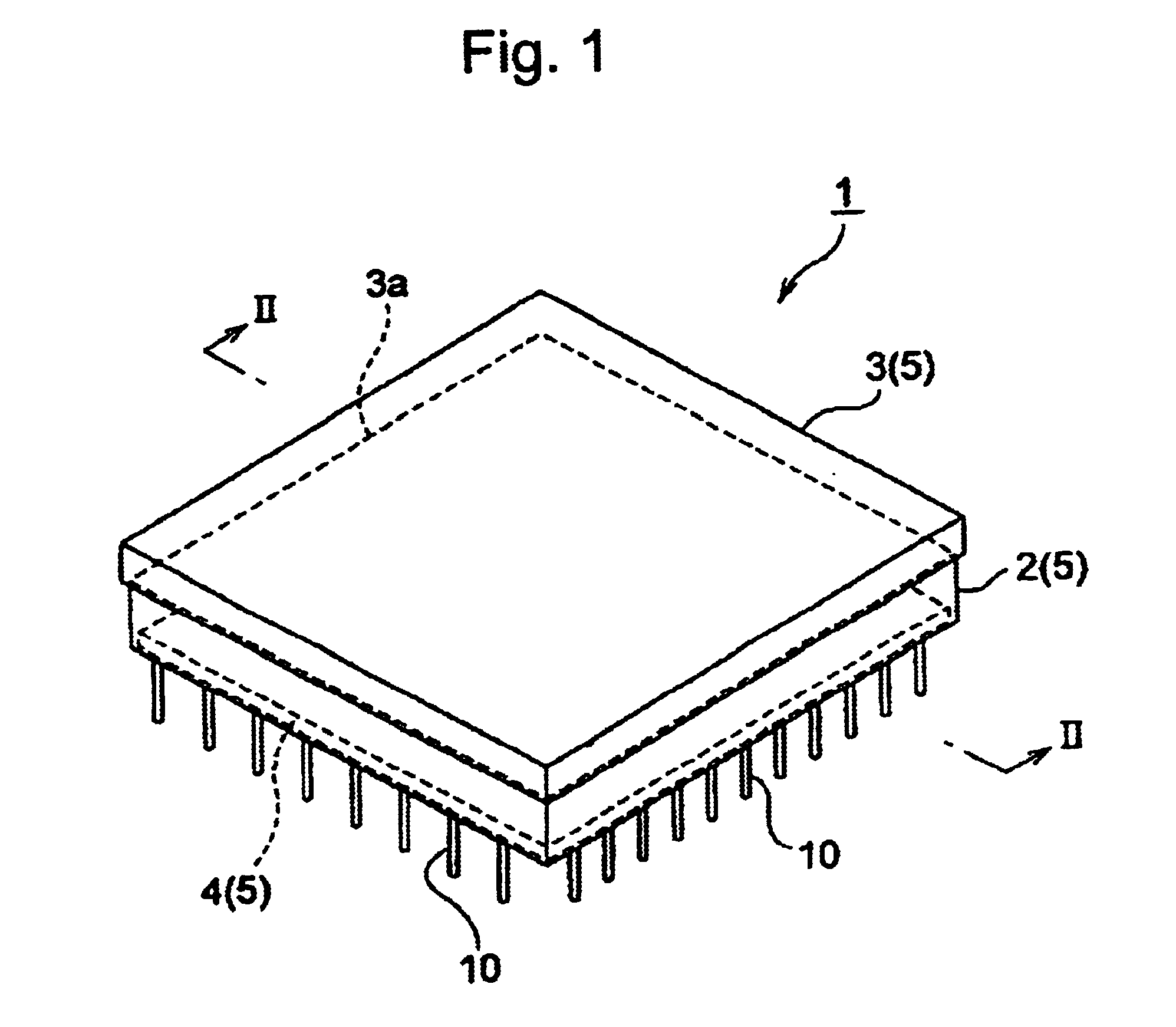
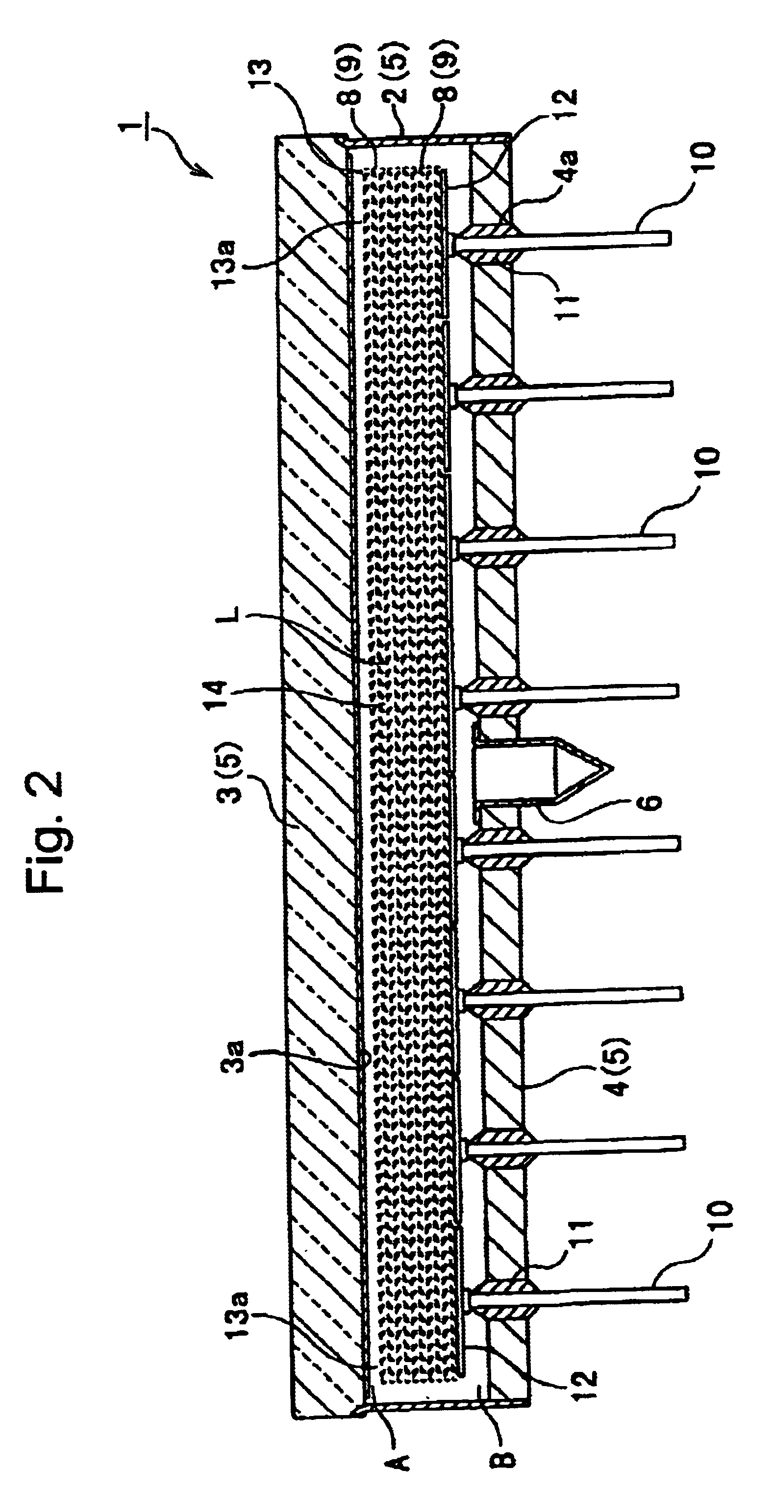
FIG. 1 is a perspective view showing a photomultiplier according to a first embodiment of the present invention. FIG. 2 is a cross-sectional view of the photomultiplier taken along the line II—II in FIG. 1. A photomultiplier 1 shown in these drawings includes a side tube 2 shaped substantially like a rectangle and formed of a metal material (such as Kovar metal or stainless steel). A light receiving faceplate 3 formed of a glass material (such as Kovar glass or quartz glass) is fused to one open end A of the side tube 2. A photocathode 3a for converting...


PUM


Abstract

A dynode (8) constituting an electron multiplier or a photomultiplier is provided with eight rows of channels (15) each defined by an outer frame (16) and a partitioning part (17) of the dynode (8). In each channel (15), a plurality of electron multiplying holes (14) are arranged. In specified positions of the outer frame (16) and the partitioning part (17) of the dynode (8), glass receiving parts (21) wider than the outer frame (16) and the partitioning part (17) are provided integrally with the dynode (8). Glass parts (22) are bonded to all the glass receiving parts (21). The glass parts (22) are bonded by applying glass to the glass receiving parts (21) and hardening the glass and each have a generally dome-like convex shape. Each dynode (8) is formed after the dome-like glass part (22) is bonded to the glass receiving part (21).

Description

TECHNICAL FIELDThe present invention relates to an electron multiplier and photomultiplier including an electron multiplying unit formed by a plurality of stacked dynodes. A photomultiplier is a vacuum tube including a light-receiving faceplate, a photocathode, an electron multiplying unit, and anodes that functions to detect light incident on the faceplate. The electron multiplier basically includes the electron multiplying unit and anodes of the photomultiplier and serves to detect ions, electrons, and the like incident on the first layer of the electron multiplying unit.BACKGROUND ARTThe electron multiplier and photomultiplier are well known in the art, as disclosed, for example, in Japanese published examined patent application No. SHO-56-1741. The photomultiplier disclosed in Japanese published examined patent application No. SHO-56-1741 includes a plurality of metal plates (dynodes) in which is formed a plurality of electron multiplying holes for multiplying electrons injected...

Claims


Application Information

Patent Timeline
IPC IPC(8): H01J43/22H01J43/00H01J43/04
CPCH01J31/507H01J43/22H01J43/045
Inventor KYUSHIMA, HIROYUKIATSUMI, AKIRASHIMOI, HIDEKI
Owner HAMAMATSU PHOTONICS KK
Why Eureka
Try Eureka