Parallel link manipulator and its control device

a manipulator and parallel link technology, applied in the field of manipulators, can solve the problems of affecting the accuracy of the transfer of the article, and reducing the life expectancy of the link member, so as to reduce the mathematical burden of converting

Inactive Publication Date: 2005-01-11
MURATA MASCH LTD
View PDF7 Cites 11 Cited by
  • Summary
  • Abstract
  • Description
  • Claims
  • Application Information

AI Technical Summary

Benefits of technology

With the control device for the parallel manipulator according to the present invention, when forward kinematic conversion is used to determine the estimated values for the task coordinate variables from the driving joint coordinate variables, the inverse matrix of the Jacobian matrix need not be used. Instead, the transposed matrix of the Jacobian matrix may be used. The transposed matrix of the Jacobian matrix can be easily determined once the Jacobian matrix is determined. This reduces mathematical burdens in converting the driving joint coordinates into the task coordinate variables. Further, through the lemmas and simulations described in the embodiments, the inventor has confirmed that this configuration enables the task coordinate variables to be estimated.

Problems solved by technology

As a result, deformation such as bending occurs in the link members, thus hindering the article from being transferred to an exact position.
Further, the life expectancy of the link members is shortened.
These disadvantages are more marked as the load of the article to be handled increases.
Consequently, it has hitherto been difficult to efficiently and accurately transfer heavy articles.
It is expected that the parallel link manipulator enables rigid and accurate linear high-speed movement from the current position to a target position, which movement is difficult to achieve with conventional serial mechanisms.
However, since the parallel mechanism has the driven joints, forward kinematic calculations are difficult.
It is thus a heavy mathematical burden to evaluate the values of the inverse matrix in connection with the respective values of the task coordinate variables.
Such a mathematical burden may hinder the parallel mechanism from being put to practical use.

Method used


Image

  • Parallel link manipulator and its control device
  • Parallel link manipulator and its control device
  • Parallel link manipulator and its control device

Examples


Embodiment Construction

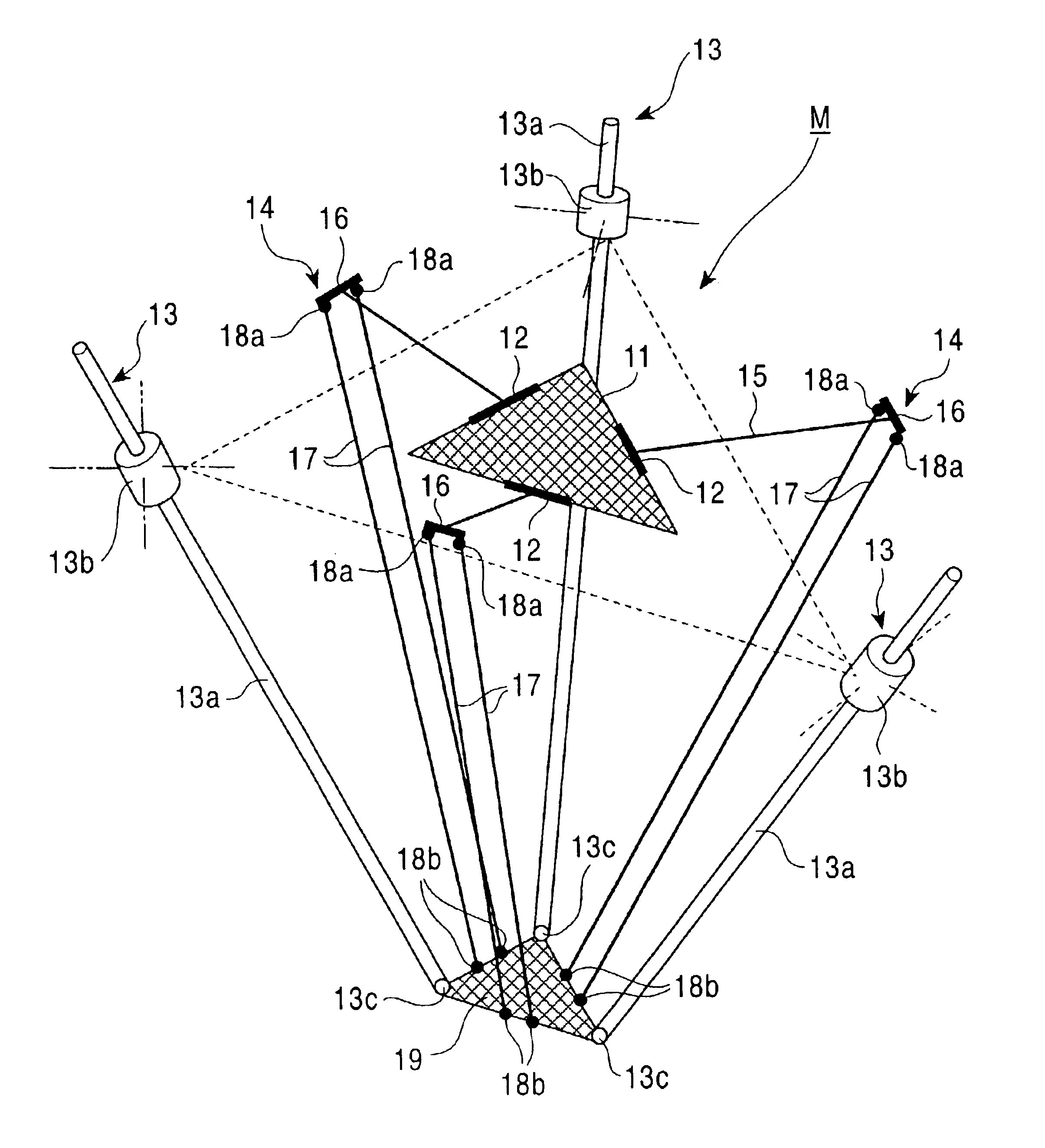
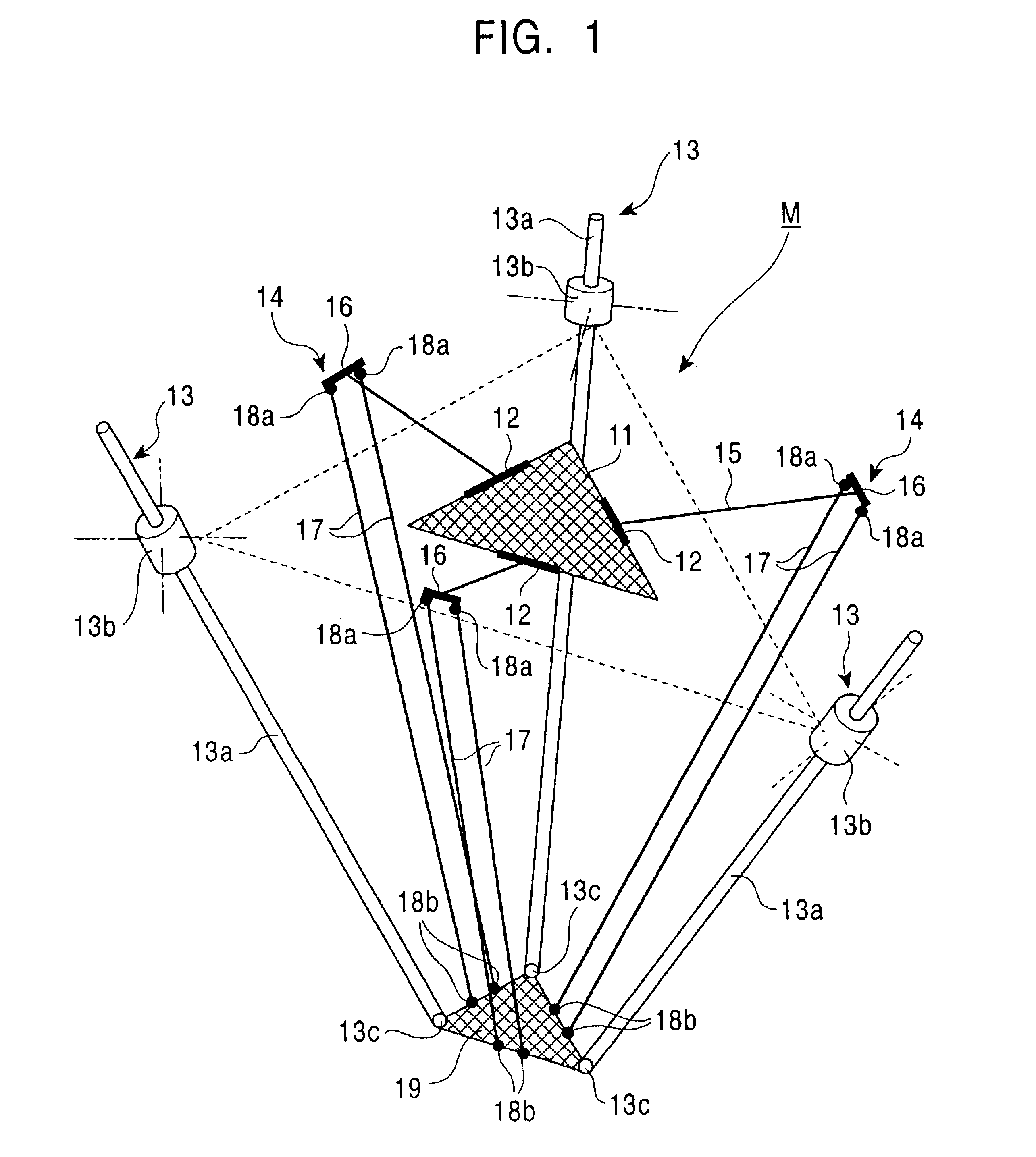
FIG. 1 shows the principle of configuration of a parallel link manipulator M according to the present invention. Three arms 14 are attached to a base section 11 used as a reference, so as to act as an auxiliary mechanism used to keep the posture of an end effecter 19 parallel with the base section 11. The end effecter 19 is supported by the leading ends of the three arms 14.

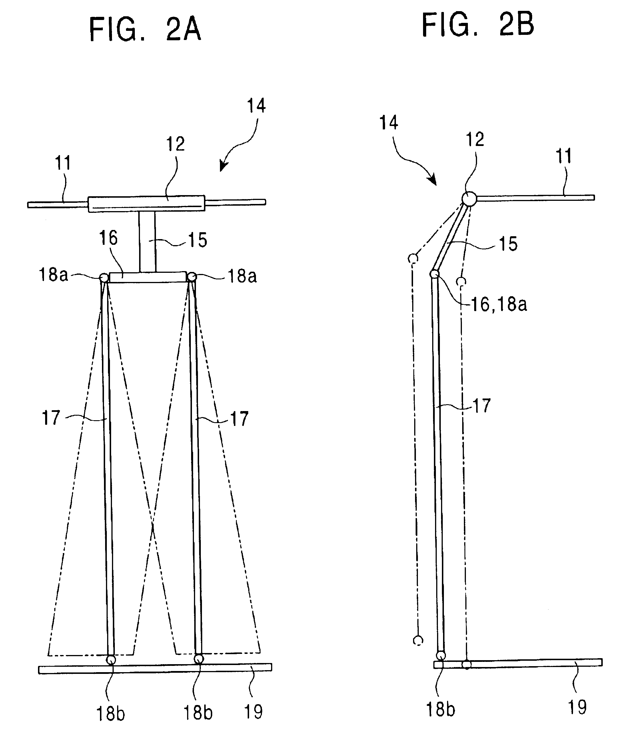
The arms 14 are attached so as to extend radially from the base section 11 in three directions at substantially equal angular intervals. Each of the arms 14 is composed of a first link section 15 consisting of a single link having one end connected to a rotating shaft 12 provided on the base section 11, and a second link section 17 consisting of a parallel link connected to the other end of the first link section 15 via another rotating shaft 16 and composed of two bars of the same length. The three rotating shafts 12 of the base section 11 are arranged in the same plane so as not be parallel with one another. Th...


PUM


Abstract

Then an end effecter is used to operate a heavy object, a large bending moment may act on arms of a manipulator to bend them. Consequently, an operating section cannot precisely control positions. Thus, according to the present invention, three arms 14 are attached to a base section 11, each of the arms 14 being composed of a first link section 15 having one end connected to a rotating shaft 12 on the base section 11 and a second link section 17 connected to the first link section 15 via another rotating shaft 16. These arms 14 support an operating section 19. The second link section 17 is connected to the rotating shaft 16 and to the operating section 19 using universal joints 18a and 18b. Direct acting driving means 13 is composed of a driving shaft 13a and a driving source that advances and retreats the driving shaft 13a. The driving shaft 13a is driven to advance and retreat to move the operating section 19 to a desired position. In this case, the operating section 19 is always kept parallel with a particular plane. Loads on the operating section 19 act in the axial directions of the driving shafts 13a. This prevents the driving shafts 13a from being bent or deformed, thus enabling precise positional control.

Description

FIELD OF THE INVENTIONThe present invention relates to a manipulator that moves an end effecter while maintaining a constant posture parallel with a particular plane.BACKGROUND OF THE INVENTIONA manipulator utilized in an industrial robot or the like determines the spatial position of an end effecter that moves, inspects, and processes an object, by controlling an arm section connected to the end effecter. It is necessary to have a high degree of freedom in order to allow the end effecter to move to an arbitrary spatial position. Among such manipulators, a so-called Stewart platform type manipulator (a degree of freedom: 6) is known in which 6 direct-acting expandable parallel link manipulators each comprising an actuator are connected to the end effecter. This manipulator has been put to practical use for machine tools.However, if the manipulator is used for a certain operation (for example, packing, aligning, or sorting articles, loading and unloading work pieces onto and from a m...

Claims


Application Information

Patent Timeline
Patent Type & Authority Patents(United States)
IPC IPC(8): B23Q1/25B23Q1/54B25J17/02B25J9/16
CPCB23Q1/5462B25J9/1623B25J9/0072B25J17/0266G05B2219/40267
Inventor OSUKA, KOICHINAKAMURA, YOICHI
Owner MURATA MASCH LTD
Why Eureka
Try Eureka