Two-pole notch filter

a notch filter and two-pole technology, applied in filters, multiple-port networks, electrical devices, etc., can solve the problems of preventing the reception of desired frequencies, affecting the stability of filter devices, and requiring a large number of components, so as to improve the stability of terns, reduce sensitivity, and widen the characteristic of inband bandwidth

Inactive Publication Date: 2005-01-11
EAGLE COMTRONICS
View PDF13 Cites 44 Cited by
  • Summary
  • Abstract
  • Description
  • Claims
  • Application Information

AI Technical Summary

Benefits of technology

The two-pole notch filter design of the present invention offers excellent long tern stability in comparison with known two-pole notch filters. The present two-pole design also provides a wider inband bandwidth characteristic, while having decrease

Problems solved by technology

Variations in ambient temperature cause the values of the passive circuit components to change, which often results in de-tuning of the filter by causing shifting of the center frequency or otherwise adversely affecting the stability of the filter device.
Drifting of the center frequency could prevent reception of the desired frequencies of the signal by unnecessarily attenuating immediately adjacent frequency bands or channels.
Although the circuit shown in FIG. 4 has great stability for a passive notch filter design, it suffers from the undesirable tradeoff that a large number of components are required. FIG. 3 shows a conventional three-pole notch filter that provides good stability, but which also employs ten parts.
However, as shown in FIG. 5a, the “tuning window” or notch characteristic associated with this particular two-pole design was extremely narrow.
Thus, the attenuation provided by the filter was insufficient to achieve the bandwidth necessary to ensure stable performance of the filter.
Known two-pole filters such as the one shown in FIG. 2 have insufficient stability to successfully function in cable or CATV applications.
The prior art two-pole notch filter shown in FIG. 2 is very sensitive to environmental c

Method used


Image

  • Two-pole notch filter
  • Two-pole notch filter
  • Two-pole notch filter

Examples


example 1

Frequency Response of a Prior Art Two-pole Filter v. Two-pole Filter of the Present Invention

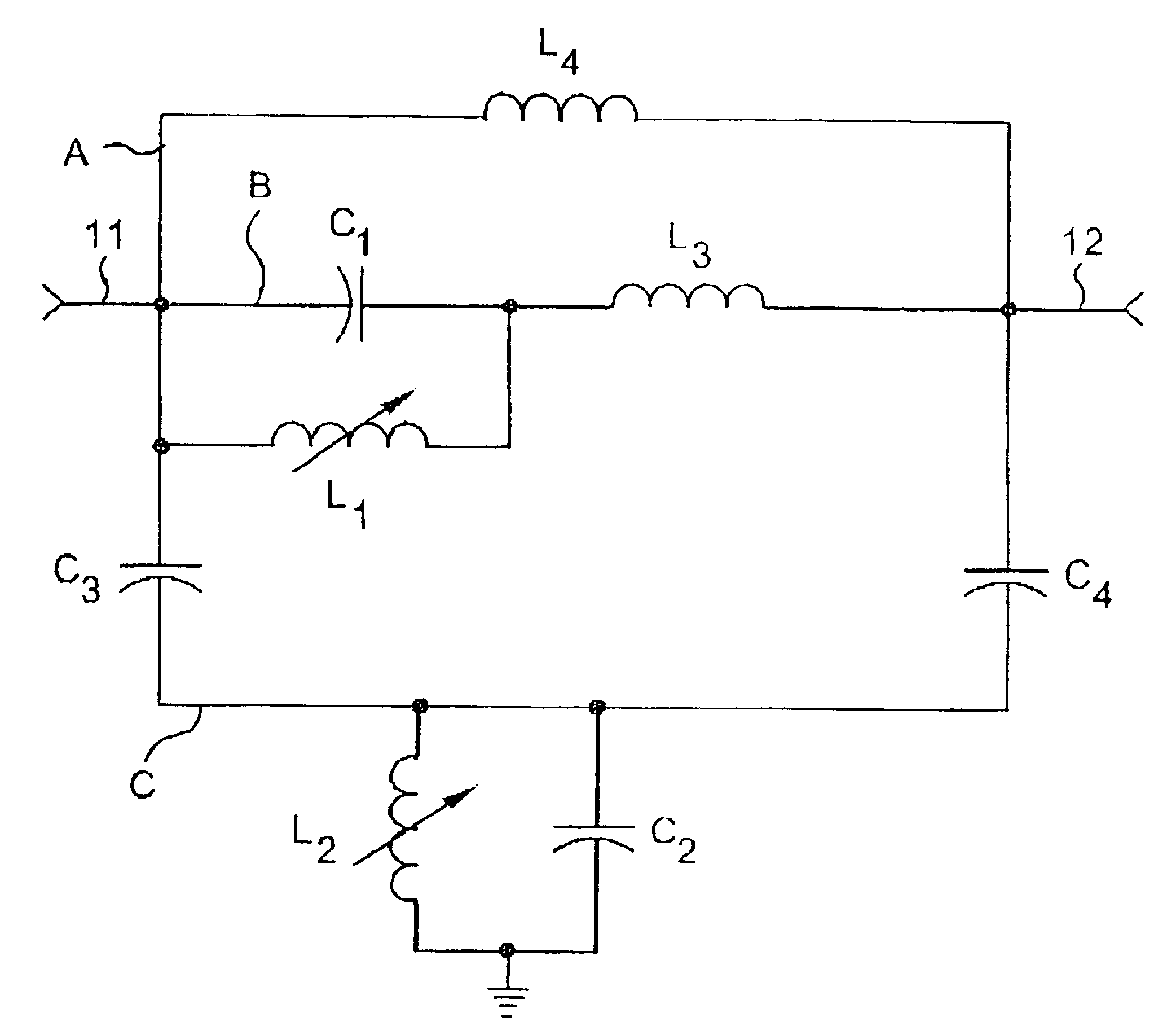
FIG. 5b shows a comparison in frequency responses between the two-pole prior art filter circuit illustrated in FIG. 2 and the notch filter of the present invention as shown in FIG. 1h, with each filter tuned to a center frequency of 169.250 MHZ. The component values used in constructing the prior art two-pole device are provided in Table 2 below.

TABLE 2InductorTurnsDiameter (inches)L14.50.180L22.50.180L32.50.068Temperature CompensationCapacitorCapacitance (pF)RatingC110N80C220N8OC31.5NPOC40.5NPO

As illustrated in FIG. 5b, the relatively wide notch provided by the two-pole notch filter of the present invention is significantly different from the narrow notch provided by the prior art two-pole notch filter. The two-pole notch filter of the present invention exhibits a significantly wider notch shape than the extremely narrow notch characteristic associated with the prior art two-pole notch filt...

example 2

Frequency Response of a Prior Art Three-pole Notch Filter v. Two-pole Notch Filter of the Present Invention

FIG. 5c shows a comparison in frequency responses between the three-pole prior art filter circuit illustrated in FIG. 3 and the notch filter of the present invention as shown in FIG. 1h, with each filter tuned to a center frequency of 169.250 MHZ. The component value used in constructing the prior art three-pole device are summarized in Table 3 below.

TABLE 3InductorTurnsDiameter (inches)L1, L2, L33.50.210L41.50.125L51.50.150Temperature CompensationCapacitorCapacitance (pF)RatingC1, C310N80 C210N150C4, C51.8NPO

FIG. 5c shows that the frequency response of the two-pole filter of the present invention is somewhat more narrow or sharp than the frequency response notch provided by an exemplary prior art three pole notch filter. Nevertheless, the two-pole notch filter still provides adequate attenuation in a sufficient bandwidth surrounding the center frequency to ensure stability. Mo...

example 3

Frequency Response of a Prior Art Four-pole Filter v. Two-pole Filter of the Present Invention

FIG. 5d shows a comparison in frequency responses between the four-pole prior art filter circuit illustrated in FIG. 4 the notch filter of the present invention as shown in FIG. 1h, with each filter tuned to a center frequency of 169.250 MHZ. The component values used in constructing the two prior art two-pole devices are summarized in Table 4 below.

TABLE 4InductorTurnsDiameter (inches)L1, L44.50.180L2, L32.50.180L5, L62.50.068Temperature CompensationCapacitorCapacitance (pF)RatingC1, C410N80C2, C320N8OC5, C81.5NPOC6, C70.5NPO

FIG. 5d illustrates that the two-pole notch filter of the present invention offers performance that is virtually identical to that of the known four pole devices, but utilizes only eight passive components. The two-pole notch filter of the present invention provides comparable attenuation, bandwidth and stability in comparison to the four-pole filter, which requires fo...


PUM


Abstract

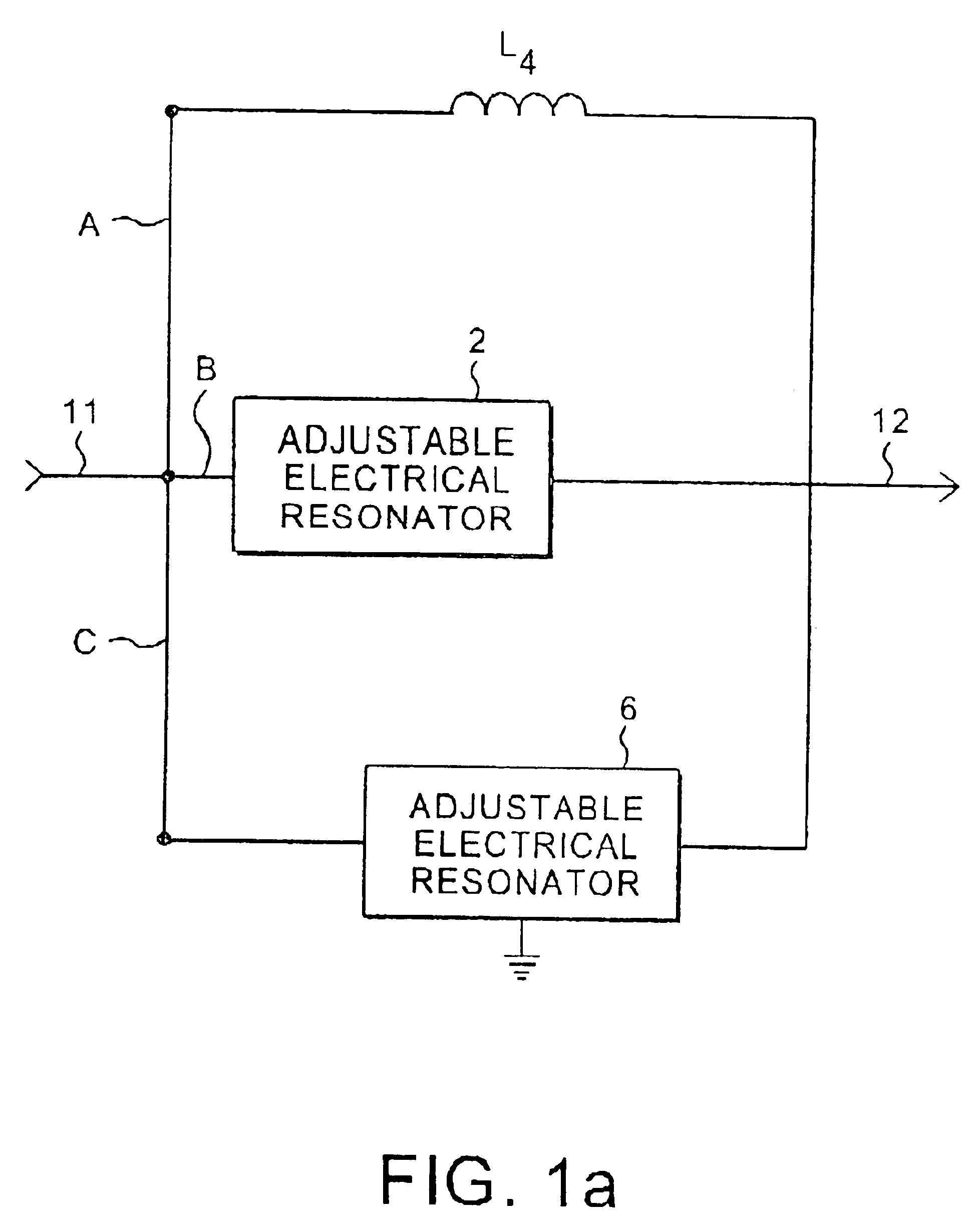
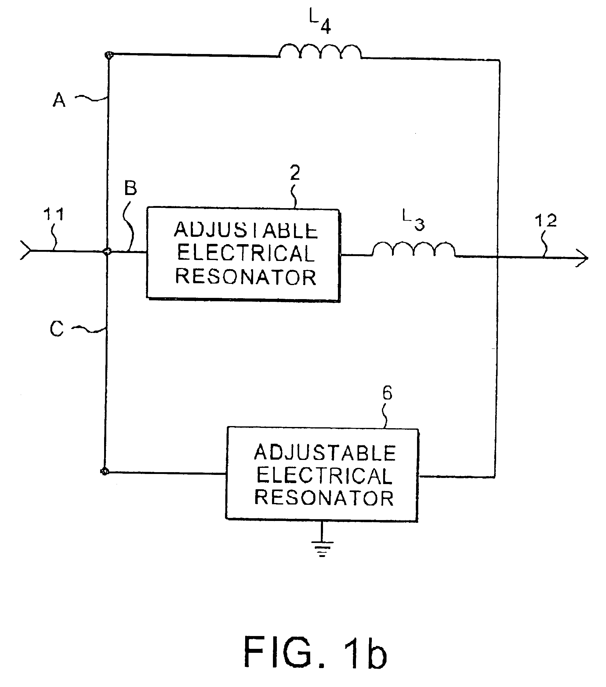
A tunable top-pole passive notch circuit for attenuating select frequencies of a multi-frequency CATV signal. The circuit includes an input for receiving a multi-frequency CATV signal, and an output for transmitting a portion of the multi-frequency CATV signal, A filter network for attenuating a band of frequencies from the multi-frequency signal is distributed been the input and the output. The filter network includes three parallel branches A, B, and C, each being arranged in series connection between the input and the output. Branch A includes an inductor. Branch B includes an adjustable parallel tank circuit Branch C includes a second adjustable electrical resonator. The filter has frequency response characteristics that are more stable than prior art two-pole notch filters, and similar to the response characteristics of more complex three pole or four pole notch filters. The two-pole tunable notch filter circuit provides a passband response to 1 GHz.

Description

The present invention relates to the art of electronic notch filters, and particularly to tunable passive notch filters suitable for use in attenuating one or more frequency components responsible for scrambling signals present in a signal of a single television channel. Such scrambling signals are typically included in a television channel signal to prevent intelligible reception of the video and / or audio portion thereof. Tuned notch filters are used to remove the scrambling signal from the television channel signal to thereby allow reception of the television channel signal (i.e., positive trapping). Such filters may also be utilized for negative trapping to reject certain frequencies within a television channel bandwidth to prevent reception of information through that channel.BACKGROUND OF THE INVENTIONElectronic circuits are often used to attenuate a selected band of frequencies while passing a larger band of frequencies. Filters employed for this purpose are commonly known as ...

Claims


Application Information

Patent Timeline
IPC IPC(8): H03H7/01
CPCH03H7/0153H03H7/1791H03H7/1725H03H7/1783H03H2007/013H03H2210/015
Inventor ZENNAMO, JR., JOSEPH A.
Owner EAGLE COMTRONICS
Why Eureka
Try Eureka