Sonar beamforming system

a beamforming system and beam technology, applied in the field of sonar beamforming systems, can solve the problems of most difficult military and commercial applications, and achieve the effects of facilitating the use of batteries, improving imaging, and low power attributes

Inactive Publication Date: 2005-01-11
TERATECH CORP
View PDF61 Cites 68 Cited by
  • Summary
  • Abstract
  • Description
  • Claims
  • Application Information

AI Technical Summary

Benefits of technology

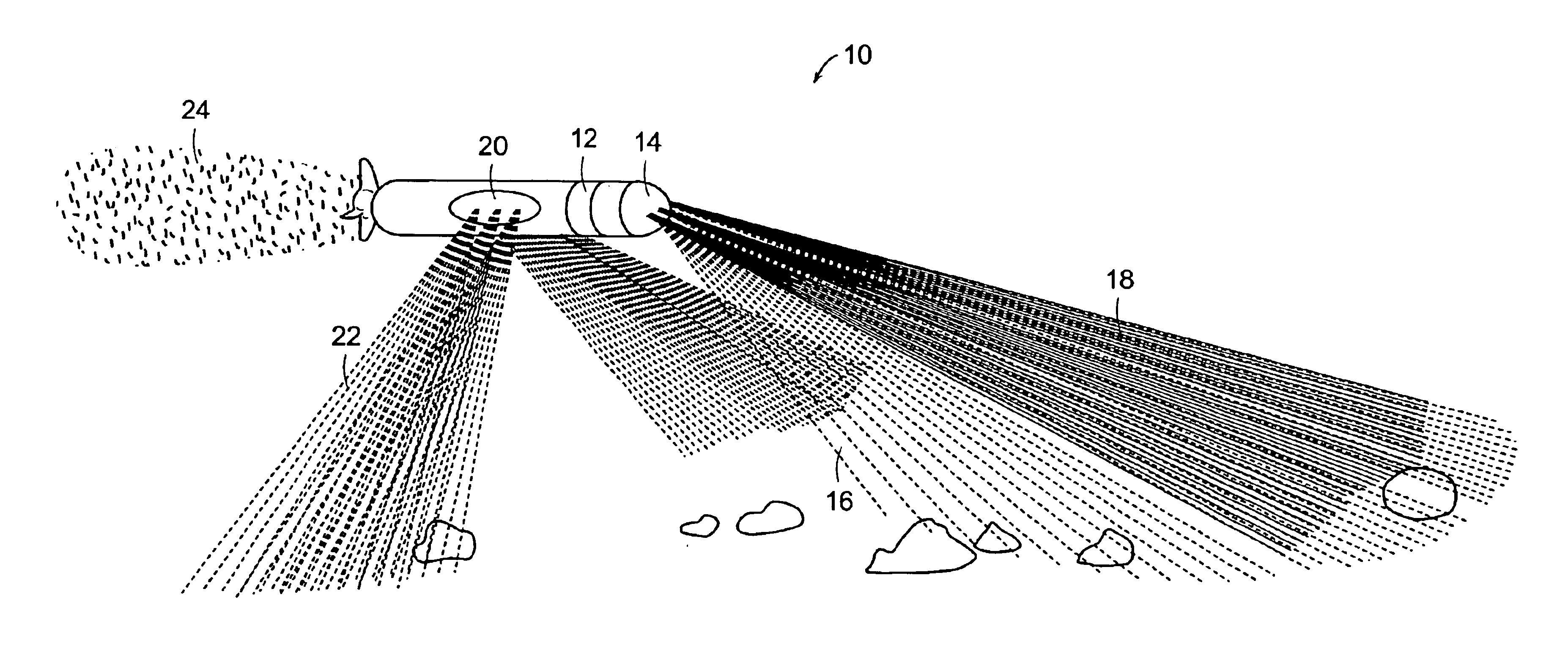
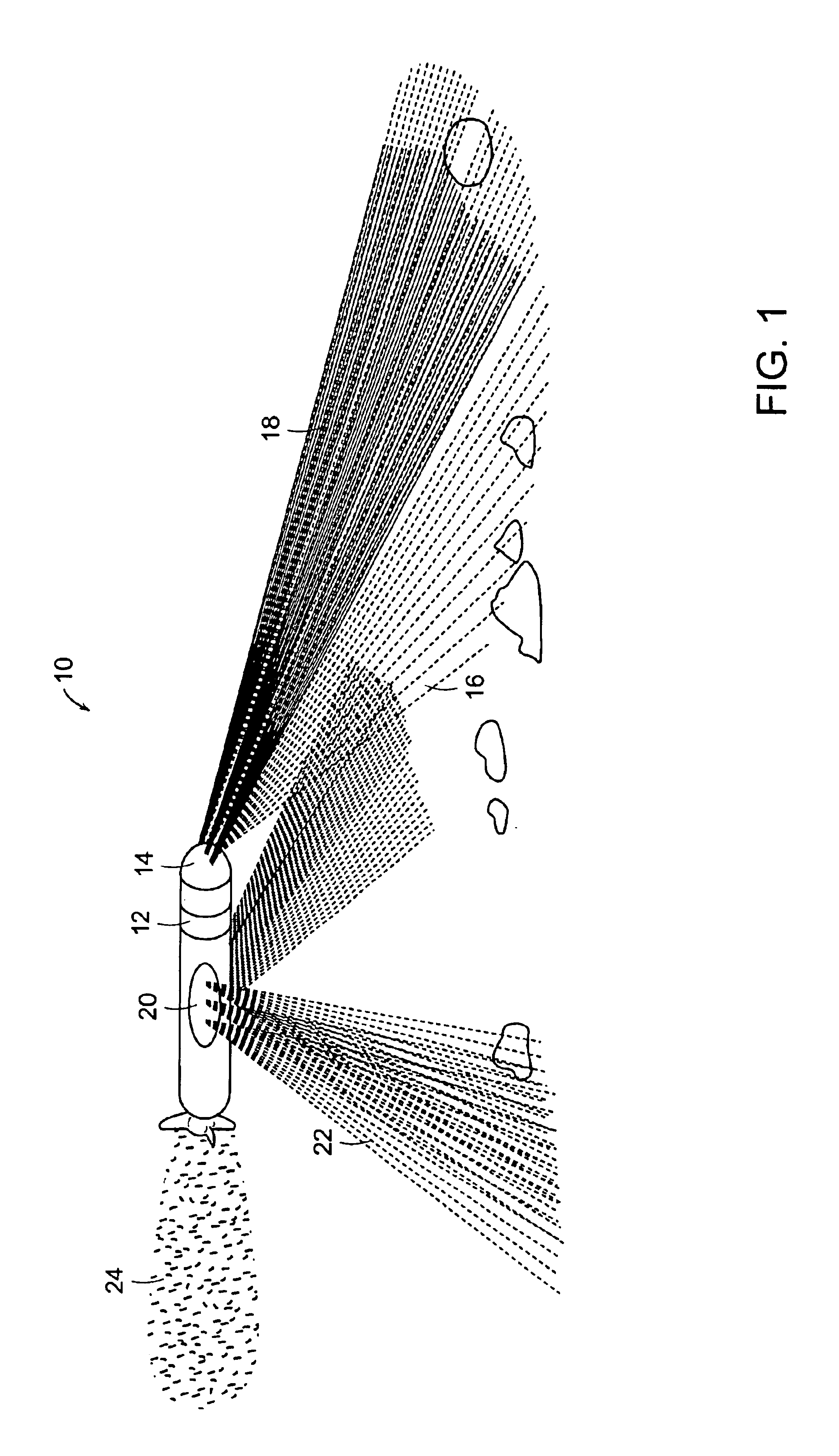
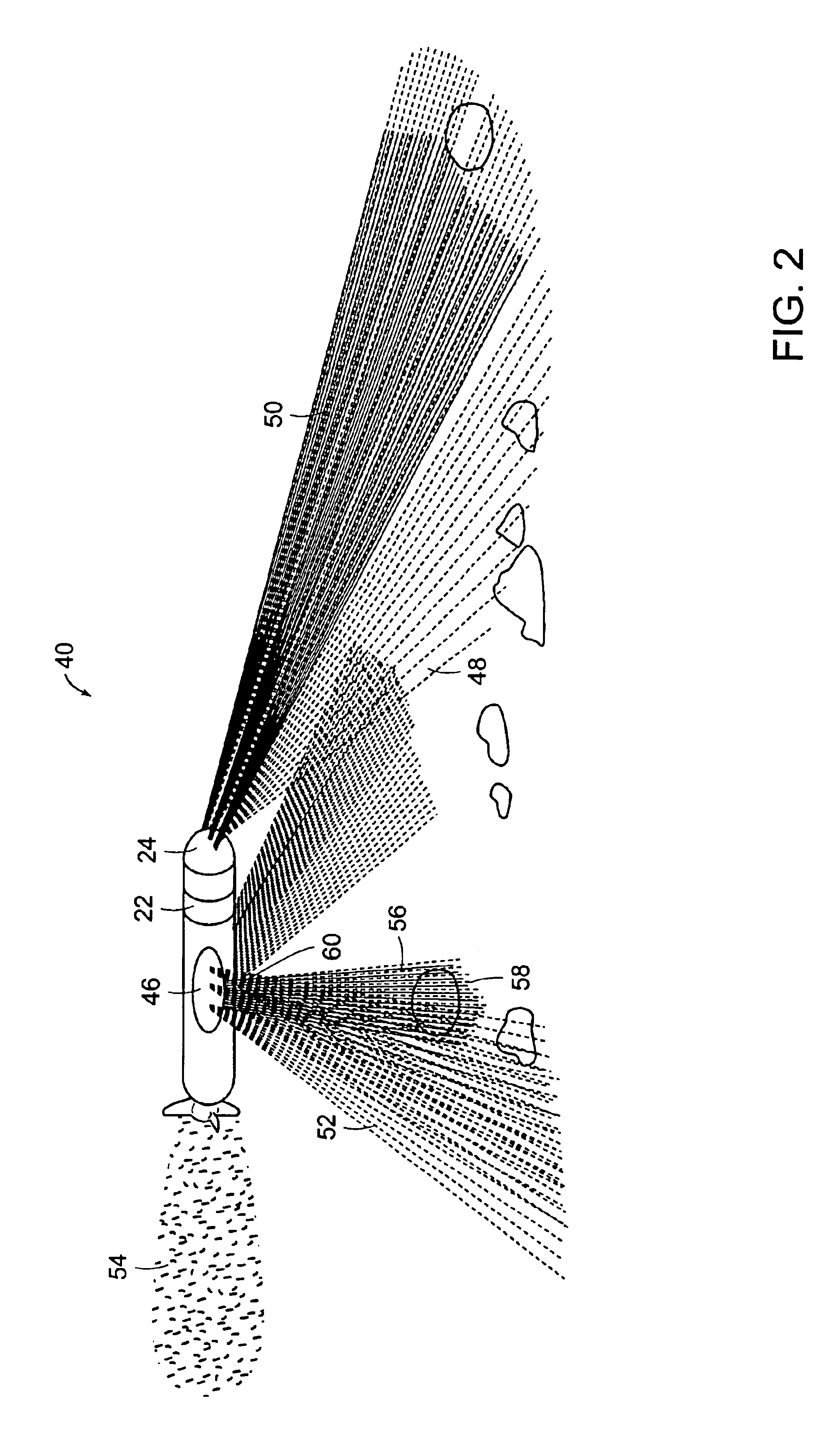
[0008]In accordance with a preferred embodiment of the present invention, the sonar imaging systems such as, for example, the forward-looking scan, the side-looking sonar and downward-looking sonar use charge-domain-processing (CDP) such as charge coupled device (CCD / CMOS) integrated circuits that allow electronic lenses to focus reflected energy following detection by a one-dimensional array. The low power attributes of CCD / CMOS technology in beamformers facilitate the use of batteries to provide the life span of missions. Further, beamformers are used to emulate an acoustic lens for the sonar and are made smaller with fewer mechanical parts that are susceptible to failure. Electronic beamformers provide better imaging with minimal or no reflection artifacts.

Problems solved by technology

In waters up to 150 meters deep it is often the most difficult for military and commercial applications, as personnel need to traverse water containing underwater mines and obstructions.

Method used


Image

  • Sonar beamforming system
  • Sonar beamforming system
  • Sonar beamforming system

Examples


Embodiment Construction

e with a preferred embodiment of the present invention;

[0014]FIG. 4 is a block diagram illustrating a sonar imaging system in accordance with another preferred embodiment of the present invention;

[0015]FIG. 5 is a block diagram illustrating a flow chart of the image fusion process of the sonar imaging system in accordance with a preferred embodiment of the present invention;

[0016]FIG. 6 is a schematic illustration of transmit and receive beam configurations of the sonar imaging system in accordance with a preferred embodiment of the present invention; and

[0017]FIG. 7 is a graphical illustration of a curvilinear array of a sonar imaging system in accordance with a preferred embodiment of the present invention.

DETAILED DESCRIPTION OF PREFERRED EMBODIMENTS

[0018]Under water research scientists continue to seek small, low power acoustic sensor technology for transition to an Autonomous Unmanned Vehicle (AUV) or an Unmanned Underwater Vehicle (UUV) such as the Semi-Autonomous Hydrographic...


PUM


Abstract

The present invention relates to sonar beamforming systems and methods, using a forward-looking sonar having transmit and receive transducer arrays with a beamforming device and at least one side-looking sonar having dynamically range-focused beams. The forward-looking sonar provides for obstacle avoidance and undersea survey. The systems include one-dimensional transmit and receive transducer arrays with beamforming electronics, a computing controller such as, for example, a personal computer host controller. The arrays and beamforming electronics can be packaged in a hermetically sealed housing unit and mounted in Unmanned Underwater Vehicles (UUV). The side-looking sonar system includes for example, 32-element, one-dimensional arrays that are mounted on either side of the UUVs. Further, a downward looking Bathymetric sonar may be mounted on the underside of the vehicle for high-resolution mapping.

Description

CROSS REFERENCES TO RELATED APPLICATIONS[0002]The present application is a continuation-in-part of U.S. patent application Ser. No. 09 / 828,266 filed on Apr. 6, 2001 now U.S. Pat. No. 6,552,964 which claims priority to U.S. patent application Ser. No. 60 / 195,587 filed on Apr. 6, 2000 and U.S. patent application Ser. No. 09 / 842,311 filed on Apr. 25, 2001, the contents of these applications being incorporated herein by reference in their entirety.BACKGROUND OF THE INVENTION[0003]In numerous applications there is a need to perform sonar beamforming operations to acquire spatial information regarding a particular area of interest. Sonar systems make use of sensor arrays to process underwater acoustic signals to determine the location of a noise source. Array processing techniques for isolating received signals are known as beamforming and when the same or analogous principles are applied to focus the transmission of signals, the techniques are referred to as beamsteering. Various systems...

Claims


Application Information

Patent Timeline
Patent Type & Authority Patents(United States)
IPC IPC(8): G01S15/89G01S15/00G01S15/93G01S7/521G10K11/34G10K11/00H01Q3/26H01Q25/00
CPCG01S7/521G01S15/8904G01S15/93H01Q25/00G10K11/346H01Q3/26H01Q3/2682G10K11/34
Inventor CHIANG, ALICE M.BROADSTONE, STEVEN R.
Owner TERATECH CORP
Why Eureka
Try Eureka