Control apparatus for cutting machine, cutting machine and cutting method

a control apparatus and cutting machine technology, applied in the direction of program control, total factory control, instruments, etc., can solve the problems of difficult to cut precisely, the angle between the cutting tool b>2/b> and the work to be cut (a cutting angle , drawings) is not constant, etc., and achieves the effect of easy calculation of the coordinates of the turret axis b

Inactive Publication Date: 2005-01-11
DMG MORI SEIKI CO LTD
View PDF7 Cites 49 Cited by
  • Summary
  • Abstract
  • Description
  • Claims
  • Application Information

AI Technical Summary

Benefits of technology

In view of the above, objects of the present invention are to enable cutting processes to be performed always at a same cutting angle β, and to enable calculation of the coordinates of the

Problems solved by technology

However, there has been a problem that when an arc-shaped surface is cut while keeping the angle of the turret 1 in this manner, an angle between the cutting tool 2 and the work to be cut (a cutting angle β shown in the drawings) is not constant.
In this manner, unless the cutting angle β is stabilized in the single cutting process, it will be difficult to cut precisely.
For this r

Method used


Image

  • Control apparatus for cutting machine, cutting machine and cutting method
  • Control apparatus for cutting machine, cutting machine and cutting method
  • Control apparatus for cutting machine, cutting machine and cutting method

Examples


Embodiment Construction

(A: Cutting Machine)

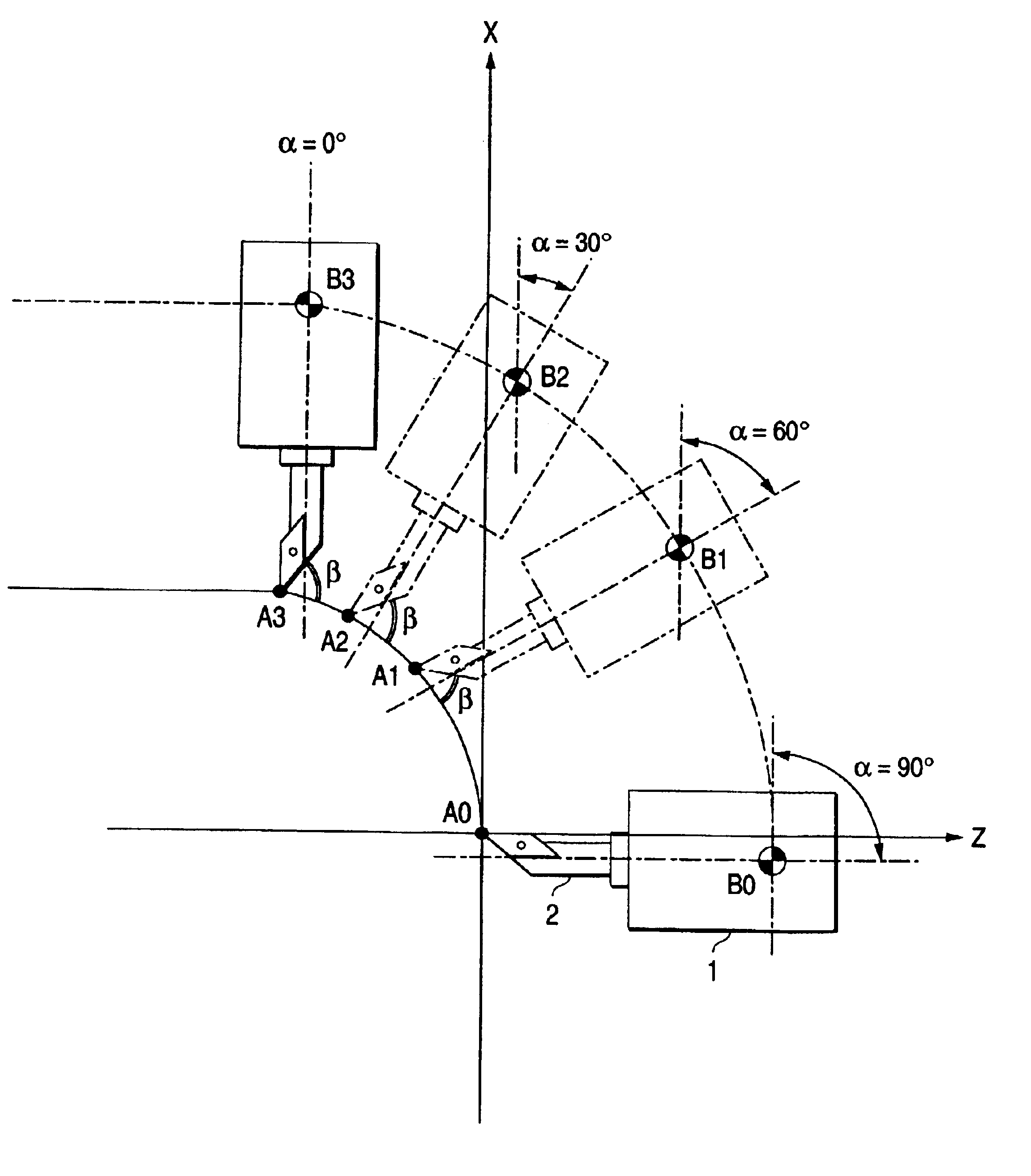
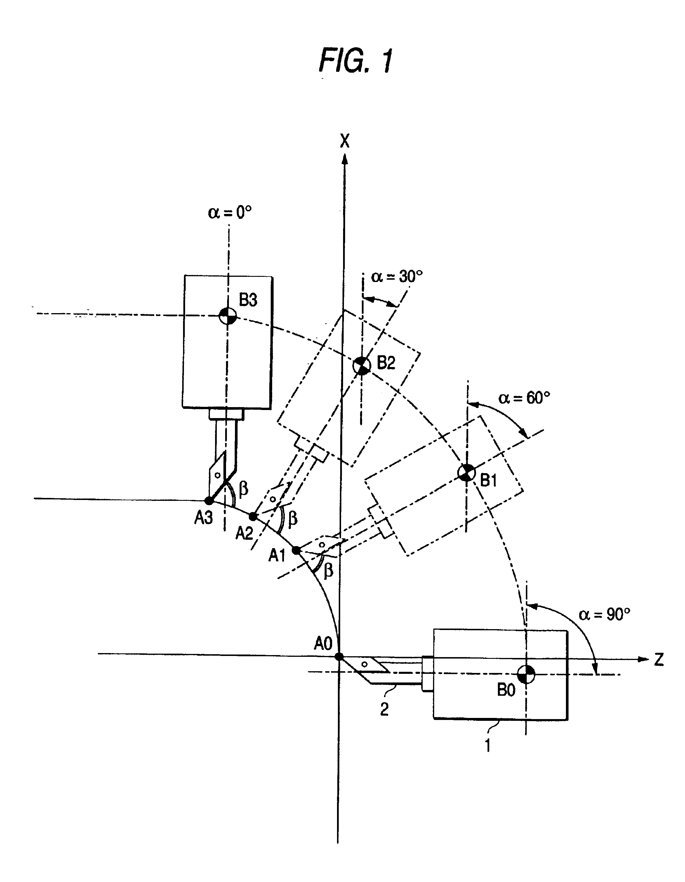
This invention relates to a cutting machine, and a control apparatus for the same. An embodiment of a turret 1 to be controlled by this control apparatus is shown in FIG. 1.

FIG. 1 shows a state in which a cutting edge of a cutting tool 2 has moved from A0 to A3 along a surface of a work to be cut. There are also shown a Z-axis and an X-axis which are coordinates intersecting at a right angle. Values of the coordinates are determined by setting a point of intersection of the X-axis and the Z-axis as a point of origin. An upward direction of the X-axis is set to be positive, and a rightward direction of the Z-axis is set to be positive.

The turret 1 is mounted on a main body of the cutting machine. The turret 1 is capable of rotating about a point B (a turret axis B) in FIG. 1, and can be indexed at arbitrary positions. A structure of the turret is the same as in the related art and therefore, omitted in the drawing.

Four points A0 to A3 are shown as data of the cutt...


PUM


Abstract

This invention relates to a control apparatus for numerical control in a cutting machine having a turret which can be rotated to arbitrary positions, and characterized by including means for obtaining turret axis data (ΔX, ΔZ) from reference offset values (X0, Z0) corresponding to a length from a cutting edge to a turret axis B, turret angle data α, and cutting edge data (m, n), and moving the turret on the basis of these turret axis data (ΔX, ΔZ) to perform a cutting.

Description

BACKGROUND OF THE INVENTION1. Field of the InventionThe present invention relates to a cutting machine (specifically a NC lathe or machining center) for performing various cuttings according to numerical control, and a control apparatus for the cutting machine.Particularly, this invention relates to the control apparatus for the cutting machine in which a turret 1 rotates around a turret axis B (a B-axis) so that a cutting process can be performed at an arbitrary position (capable of indexing at the arbitrary position).2. Related Art(1) Modes of controlling a cutting edge of a cutting tool 2 in a conventional cutting machine are shown in FIGS. 8 and 9. FIG. 8 shows a mode in which a cutting is performed while the turret 1 is kept at a fixed angle. FIG. 9 shows a mode in which the turret 1 is rotated according to an outer configuration of a work to be cut. Respective positions of the cutting edge are represented by a0 to a3, and positions of the turret axis B are represented by b0 to...

Claims


Application Information

Patent Timeline
IPC IPC(8): G05B19/4093B23B1/00B23Q16/02B23Q15/22G05B19/404
CPCG05B19/4093G05B2219/50285Y10T82/2502G05B2219/50353G05B2219/50297Y02P90/02
Inventor HARADA, HISAONAKAHIRA, HIROKIONO, KATSUAKI
Owner DMG MORI SEIKI CO LTD
Why Eureka
Try Eureka