
Method for monitoring the functioning of a NOx sensor arranged in an exhaust gas channel of an internal combustion engine

Inactive Publication Date: 2005-01-18
VOLKSWAGEN AG
View PDF20 Cites 23 Cited by
  • Summary
  • Abstract
  • Description
  • Claims
  • Application Information

AI Technical Summary

Benefits of technology

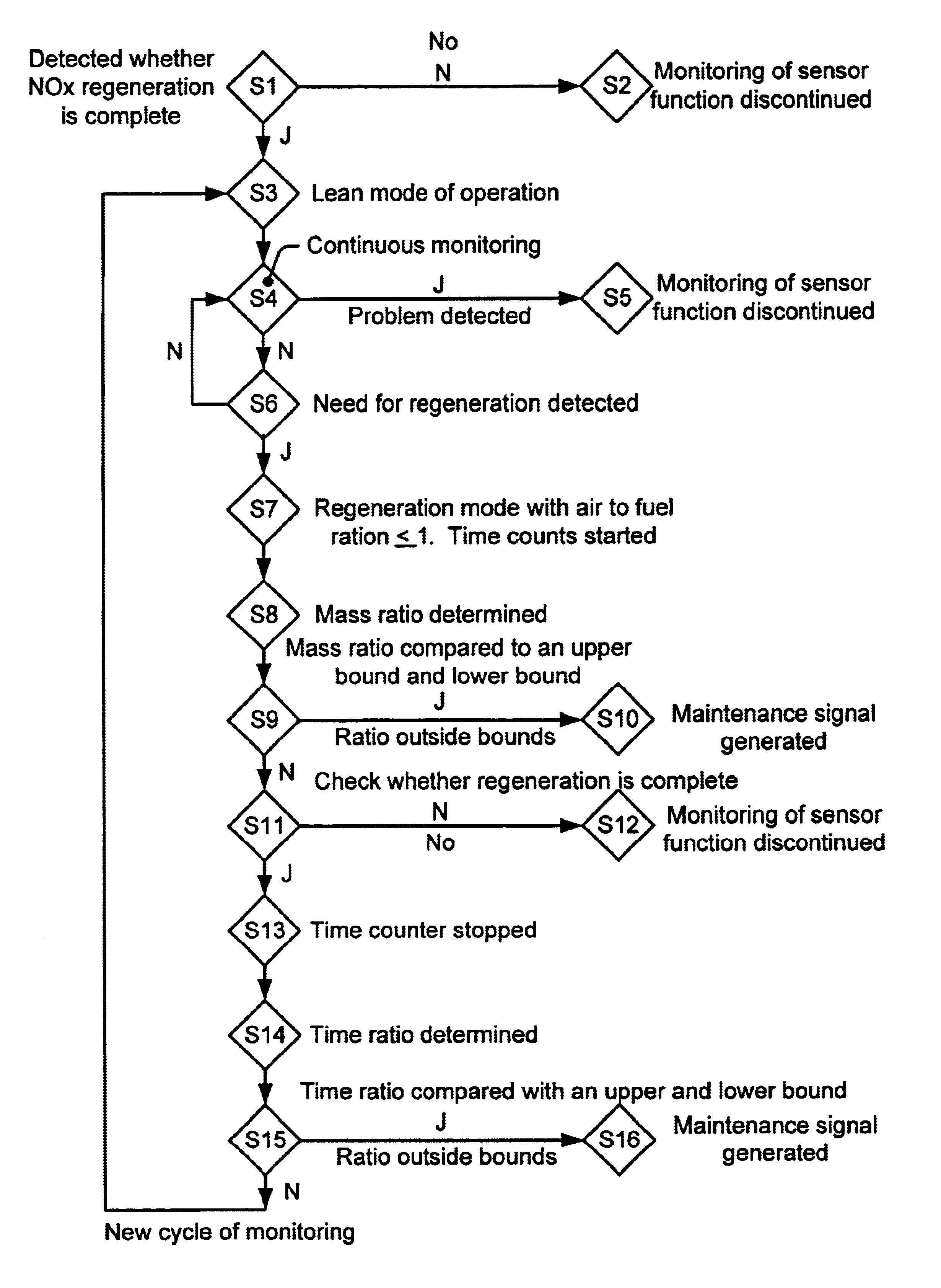
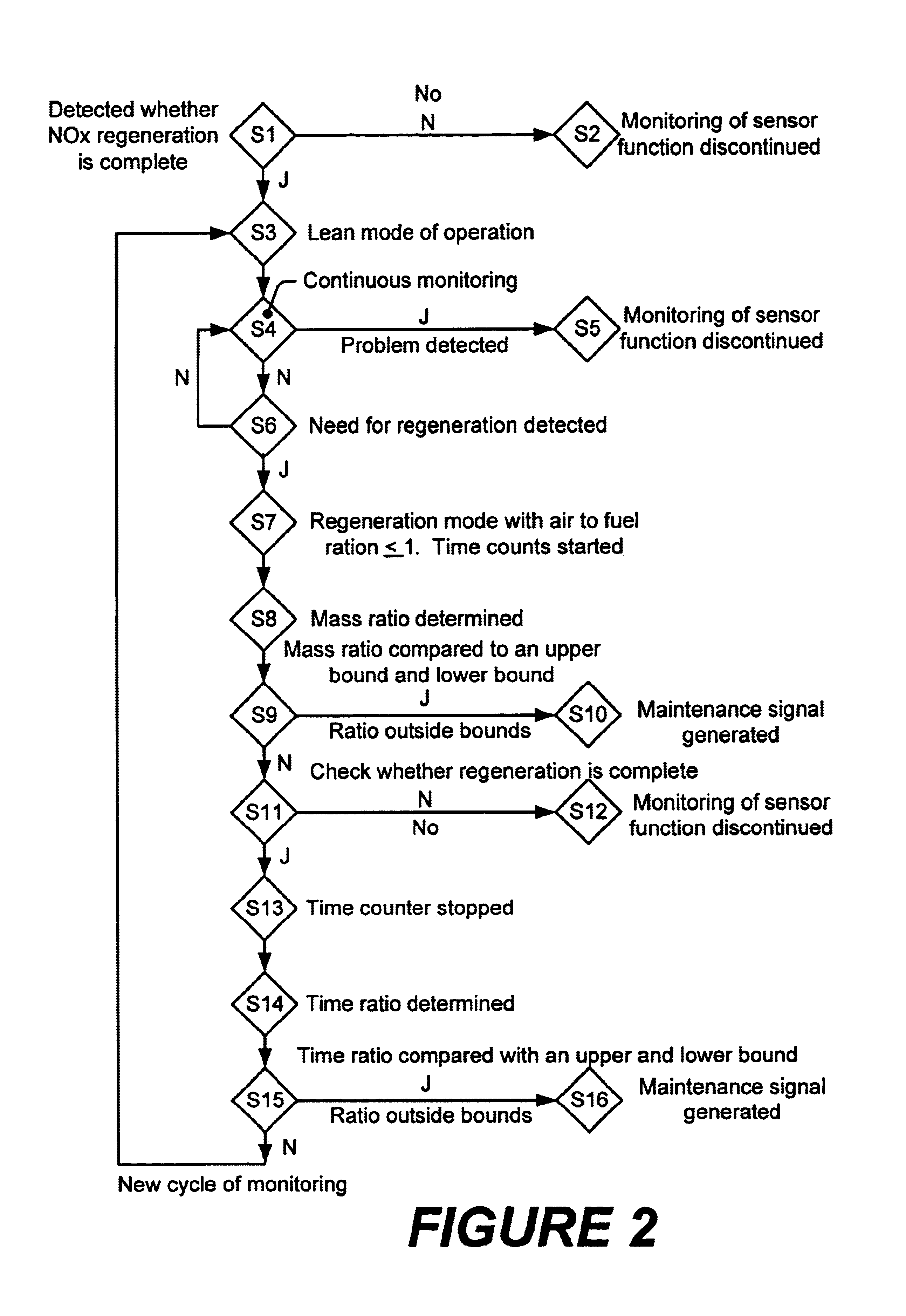
After the occurrence of a maintenance signal, in either situation, the error can be corrected by suitable measures, or the NOx sensor can be replaced if necessary. Further, it is advantageous to set the period of diagnosis to begin immediately after a complete NOx regeneration of the NOx storage catalyst and a change to a lean mode of the engine. Preferably, the period of diagnosis will end after identification of a need to regenerate the NOx storage catalyst or upon a change in regeneration mode. Monitoring the function of the NOx sensor should preferably take place only when a selected period of constant lean mode of operation of the engine has been detected. In this way, the influences from the dynamic operation of the engine on the model of the storage catalyst, that are difficult to allow for, can be avoided.

Problems solved by technology

In this case, an adequate reaction of NOx on the catalyst will no longer be ensured.
A disadvantage of this, however, is that if the NOx sensor misfunctions, high NOx emissions may occur, or NOx may be unnecessarily consumed during a premature regeneration.

Method used


Image

  • Method for monitoring the functioning of a NOx sensor arranged in an exhaust gas channel of an internal combustion engine
  • Method for monitoring the functioning of a NOx sensor arranged in an exhaust gas channel of an internal combustion engine
  • Method for monitoring the functioning of a NOx sensor arranged in an exhaust gas channel of an internal combustion engine

Examples


Embodiment Construction

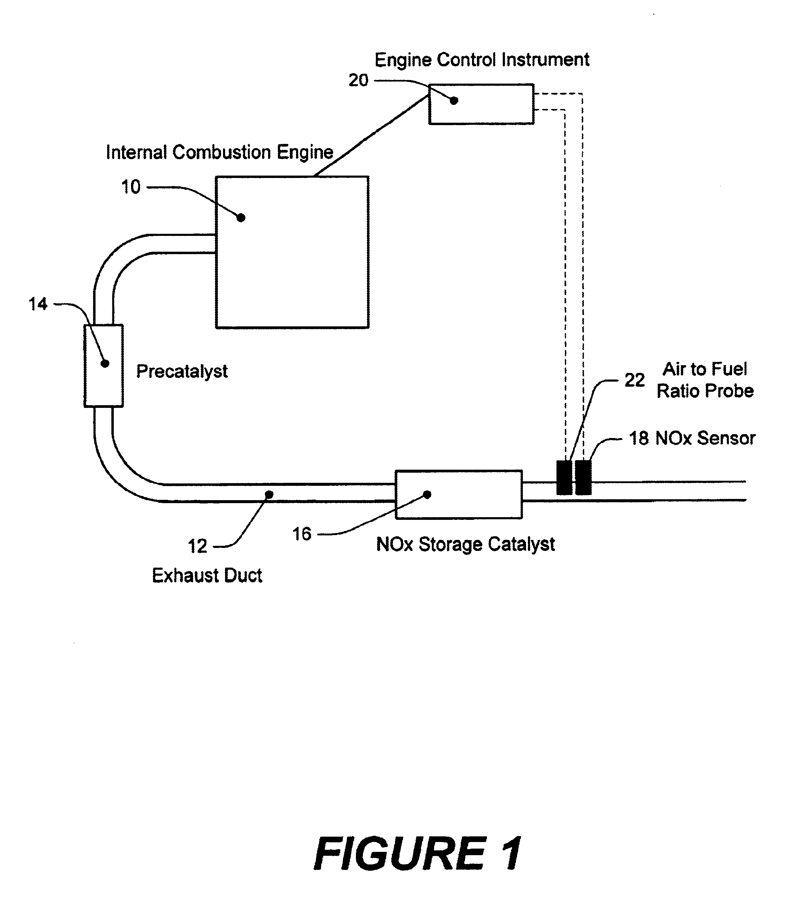
FIGS. 1 and 2 are drawings showing embodiments of the invention. FIG. 1 shows an arrangement of an internal combustion engine 10, including an exhaust duct 12, a precatalyst 14, and a NOx storage catalyst 16. The precatalyst 14, and the NOx storage catalyst 16, serve to diminish pollutant emission of the engine 10. Ordinarily, the catalysts 14 and 16 include components that make possible the oxidation of reducing agents formed during combustion, such as CO, HC or H2, by atmospheric oxygen. At least the NOx storage catalyst 16, comprises a catalyst component that makes possible the reduction of NOx, formed during the process of combustion of an air-fuel mixture, by means of the reducing agents. If the engine 10, is in a lean mode of operation, as a rule, the proportion of reducing agents in the exhaust will not be sufficient to ensure a high conversion of NOx. In lean mode, therefore, the NOx will be absorbed as nitrate by the storage component of the NOx storage catalyst 16.

The abso...


PUM


Abstract

The invention relates to a method for monitoring the functioning of an NOx sensor, which is arranged in an exhaust gas channel of an internal combustion engine and is located downstream from an NOx storage catalytic converter. The aim of the invention is to detect the faulty functioning of the NOx sensor in a simple manner in order to be able to take appropriate measures if necessary. To this end, the mass of NOx absorbed by the NOx storage catalytic converter is determined within a diagnostic period using a measurement signal of the NOx sensor. At the same time, an absorbed NOx target mass is calculated using a model for the NOx storage catalytic converter. A ratio of the NOx mass to the NOx target mass is then compared to predetermined limit values to determine the functioning of the NOx sensor. The aim of the invention is alternatively accomplished by measuring a duration time for a complete NOx regeneration of the NOx storage catalytic converter. A specified duration time is also calculated for the NOx regeneration using a model for the NOx storage catalytic converter and using a measured or calculated NOx load state. A ratio of the measured duration time to the specified duration time is then compared to predetermined limit values to determine the functioning of the NOx sensor.

Description

BACKGROUND OF THE INVENTIONThe invention relates to a process for monitoring the function of an NOx sensor arranged in an exhaust duct of an internal combustion engine. To reduce the emission of pollutants from an internal combustion engine, a known practice is to arrange suitable catalysts in the exhaust gas duct of the engine. The catalyst collects pollutants, such as CO, HC or H2 that can act as reducing agents and be oxidized by atmospheric oxygen. These reducing agents may also react with the NOx, produced during the combustion process in the engine, to form nitrogen.If the engine is operating in a lean mode the proportion of oxygen in the air-fuel mixture is increased, which is more favorable to combustion, and as a consequence the proportion of the reducing agents in the exhaust will decrease. In this case, an adequate reaction of NOx on the catalyst will no longer be ensured. As a remedy, an NOx reservoir may be arranged in the exhaust duct and combined with the catalysts to...

Claims


Application Information

Patent Timeline
IPC IPC(8): F01N11/00F02D41/02F02D41/14G01N27/417G01N33/00F01N3/08F01N9/00F01N3/00F02D45/00
CPCF01N3/0842F01N11/00F01N11/007F02D41/0275F02D41/146F02D41/1462F02D41/1463F02D41/1495G01N27/4175G01N33/0037F01N9/005Y02T10/24F01N2550/03F01N2560/026F01N2900/0422F02D2200/0806Y02T10/47Y02A50/20Y02T10/12Y02T10/40
Inventor HAHN, HERMANNLANG, AXEL
Owner VOLKSWAGEN AG
Learn More