
Device and a method for thermal sensing

a technology of thermal sensing and devices, applied in the direction of material thermal analysis, photovoltaics, electrical/magnetic means, etc., can solve the problems of cumbersome approach, lack of accuracy, heat change, etc., and achieve space-consuming design

Inactive Publication Date: 2005-01-18
TTP LABTECH
View PDF10 Cites 28 Cited by
  • Summary
  • Abstract
  • Description
  • Claims
  • Application Information

AI Technical Summary

Benefits of technology

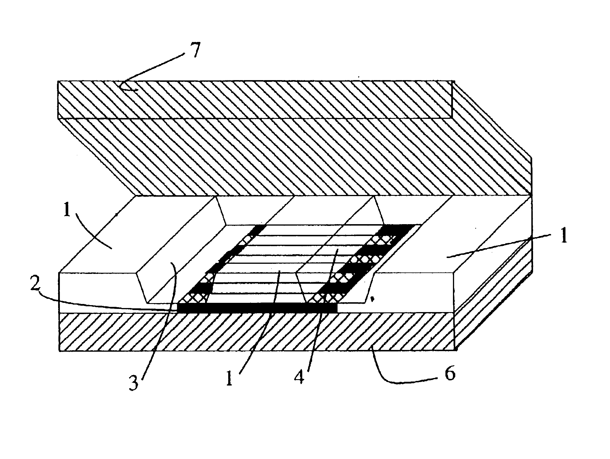
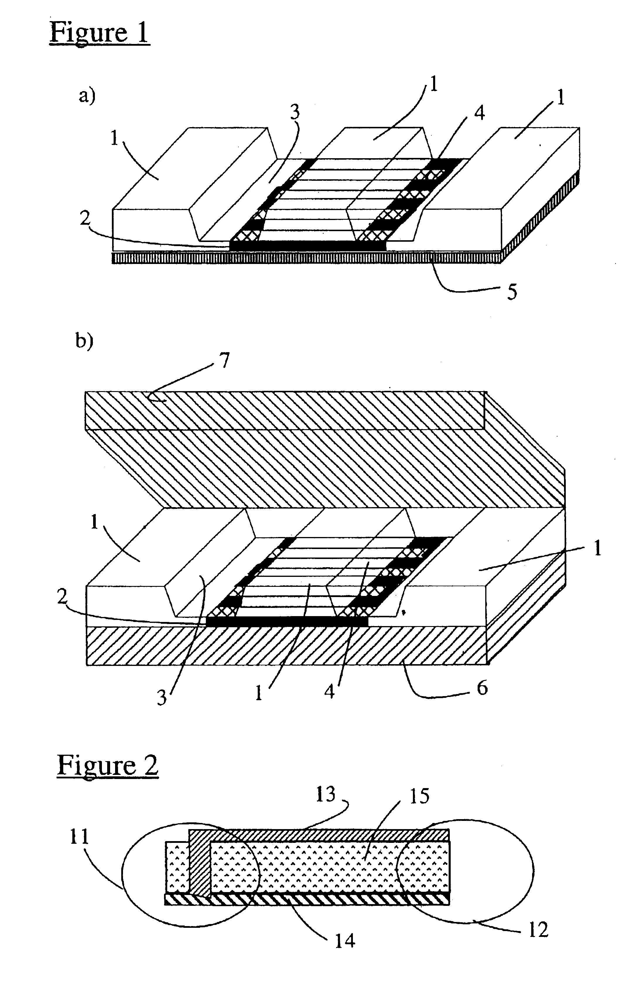
In an aspect of the invention a device is disclosed based on only one thermopile wherein said thermopile is in contact with at least parts of a substrate, e.g. a silicon wafer or the remains thereof. The cold junctions of said thermopile are coupled thermally to a first channel comprising a first substance while the hot junctions of said thermopile are coupled thermally to a second channel comprising a second substance, said first and said second channel are separated and thermally isolated one from another. Said device is capable of handling a very small amount of a substance, typically in the range from 1 microliter to 30 microliter.

Problems solved by technology

The drawbacks of these state-of-the art devices are the following.
When the potential drug candidate is effective, it will activate the genetically engineered cells which results in a heat change.
This is a cumbersome approach which lacks accuracy and demands a space consuming design.

Method used


Image

  • Device and a method for thermal sensing
  • Device and a method for thermal sensing
  • Device and a method for thermal sensing

Examples


Embodiment Construction

In relation to the appended drawings the present invention is described in detail in the sequel. Several embodiments are disclosed. It is apparent however that a person skilled in the art can imagine several other equivalent embodiments or other ways of practicing the present invention, the spirit and scope thereof being limited only by the terms of the appended claims.

A device is disclosed yielding an electrical output signal but having an input or intermediate signal of the thermal type. Said device can be used e.g. for the analysis of the activity of biological cells, chemical reactions in small volumes and other microanalytical applications. Particularly said device can be used to monitor chemical and physical processes which are accompanied by changes in heat content or enthalpy. Furthermore said device can be used to thermodynamically characterize a biological interaction as a means to rational drug design, to drug stability and drug effect studies on cells and blood.

In an emb...


PUM

PropertyMeasurementUnit
electricalaaaaaaaaaa
thermalaaaaaaaaaa
chemicalaaaaaaaaaa

Abstract

A device for thermal sensing is based on only one thermopile. The junctions of the thermopile are coupled thermally to a first region which includes a first substance while the hot junctions of the thermopile are coupled thermally to a second region which includes a second substance. The first and second regions are separated and thermally isolated from each other. The device can further include a membrane to thermally and electrically isolate the thermopile and to mechanically support the thermopile.

Description

FIELD OF THE INVENTIONThe present invention is related to a device which yields an electrical output signal but has an input or intermediate signal of the thermal type. Such a device can be used to characterize chemical and physical processes which are accompanied by changes in heat content or enthalpy. Furthermore a method is disclosed for manufacturing said device by means of micromachining which is a technique closely related to the technique used for the manufacturing of integrated circuits.BACKGROUND OF THE INVENTIONNew approaches in the combinatorial chemistry have resulted in the capability of producing millions of compounds in a short time. Analysis of each compound with respect to multiple parameters is proving to be a significant bottleneck as in e.g. M. A. Shoffner et al., Nucleic Acids Research, 1996, vol. 24, No. 2, pp. 375-9. The number of cells, the test reagent volumes, the throughput rate and the ease of use through automation are all important parameters which shou...

Claims


Application Information

Patent Timeline
Patent Type & Authority Patents(United States)
IPC IPC(8): G01K7/02
CPCG01K7/028Y10S257/93
Inventor VERHAEGEN, KATARINA
Owner TTP LABTECH
Learn More