
Blood drawing system

Inactive Publication Date: 2005-01-18
MPS CAPITAL
View PDF13 Cites 29 Cited by
  • Summary
  • Abstract
  • Description
  • Claims
  • Application Information

AI Technical Summary

Benefits of technology

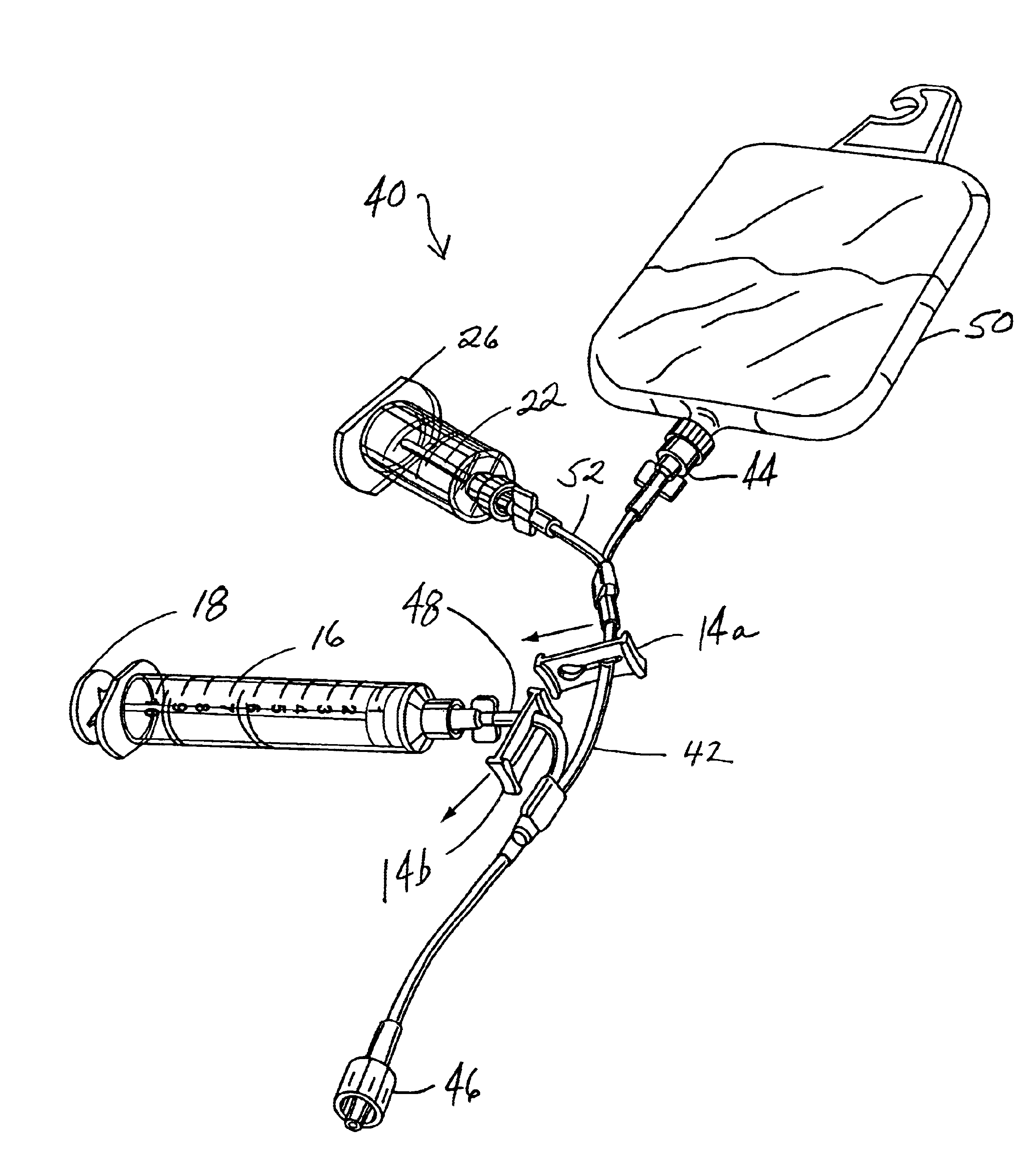
As is thus apparent, the present invention accomplishes blood transfer from a drawing syringe to a negative-pressure collection vessel through a closed network not requiring attachment of a needle to the syringe, and additionally accomplishes a closed drip-line system in which medicament liquid cleared from the drip line prior to blood withdrawal is conservedly collected for reintroduction after the blood sample has been drawn.

Problems solved by technology

However, in patients whose vascular system is fragile, the negative pressure within a vacuum tube can be excessive, and such excessive negative pressure can cause vessel collapse as suction from the vacuum tube attempts to extract a blood sample.
As is recognized to those with ordinary skill in the art, the above-described attachment of the needle to the syringe is potentially a very dangerous event because an easily-occurring finger-stick of the technician performing the task can mean the transfer of patient blood to the technician along with blood-borne disease.
As is evident, however, if the line is not first cleared of drip-liquid, any blood sample will have a high amount of such medicament liquid and therefore will not provide a true blood-only sample.
As is evident, this approach not only decreases (and wastes) the intended drip-liquid amount for the patient, but also causes loss of at least a small amount of blood from the patient as the drip line is filled with only blood for vacuum tube collection.
One or both of these disadvantages can be harmful to a patient.
In particular, if the amount of drip-liquid to be delivered to a patient is critical, such amount is automatically compromised with drip-liquid loss.
Second, if the patient is a neonatal child with a corresponding very low volume of blood, even a small blood loss which occurs during each drip line clearance can create a dangerous health hazard.

Method used


Image

  • Blood drawing system
  • Blood drawing system
  • Blood drawing system

Examples


Embodiment Construction

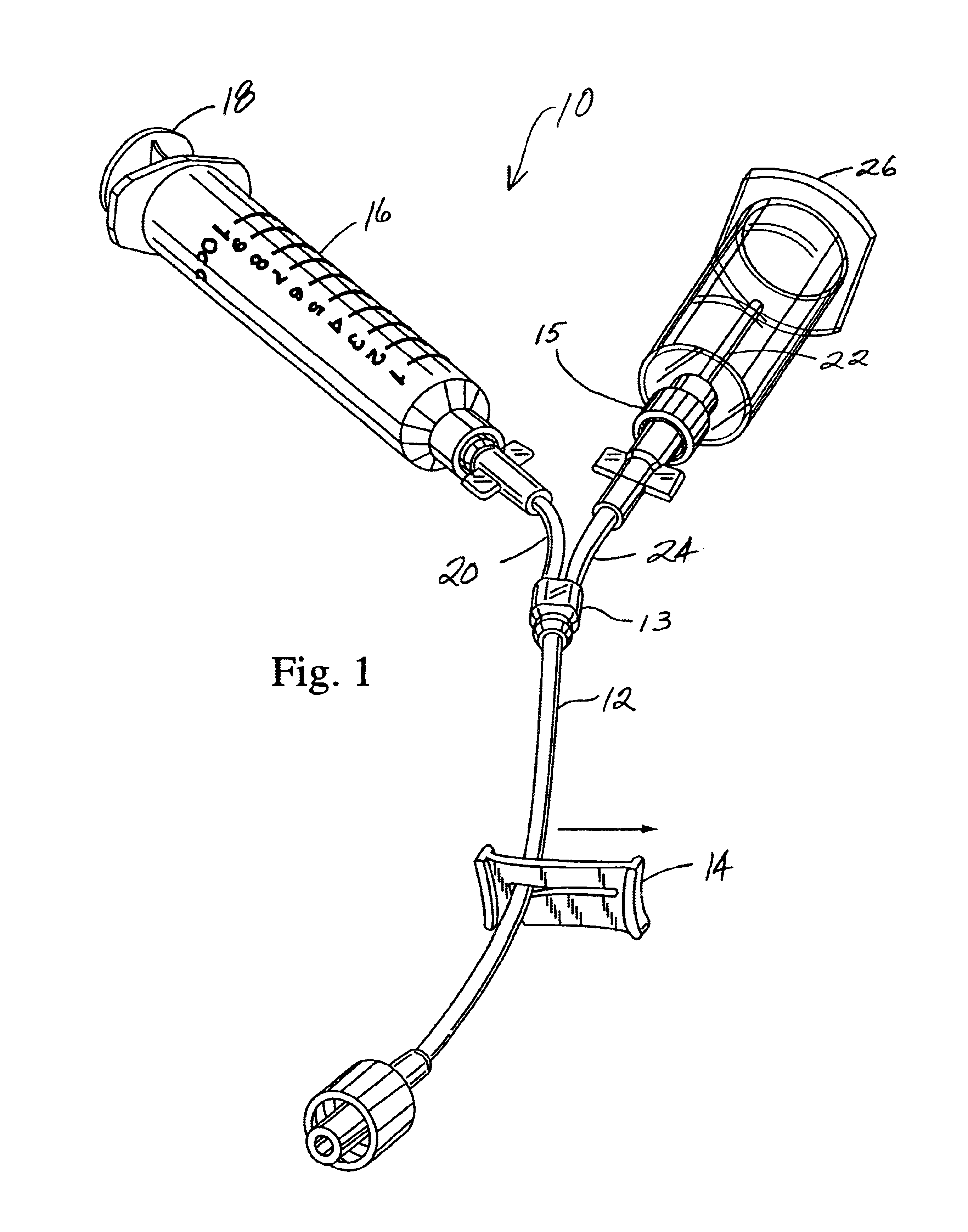
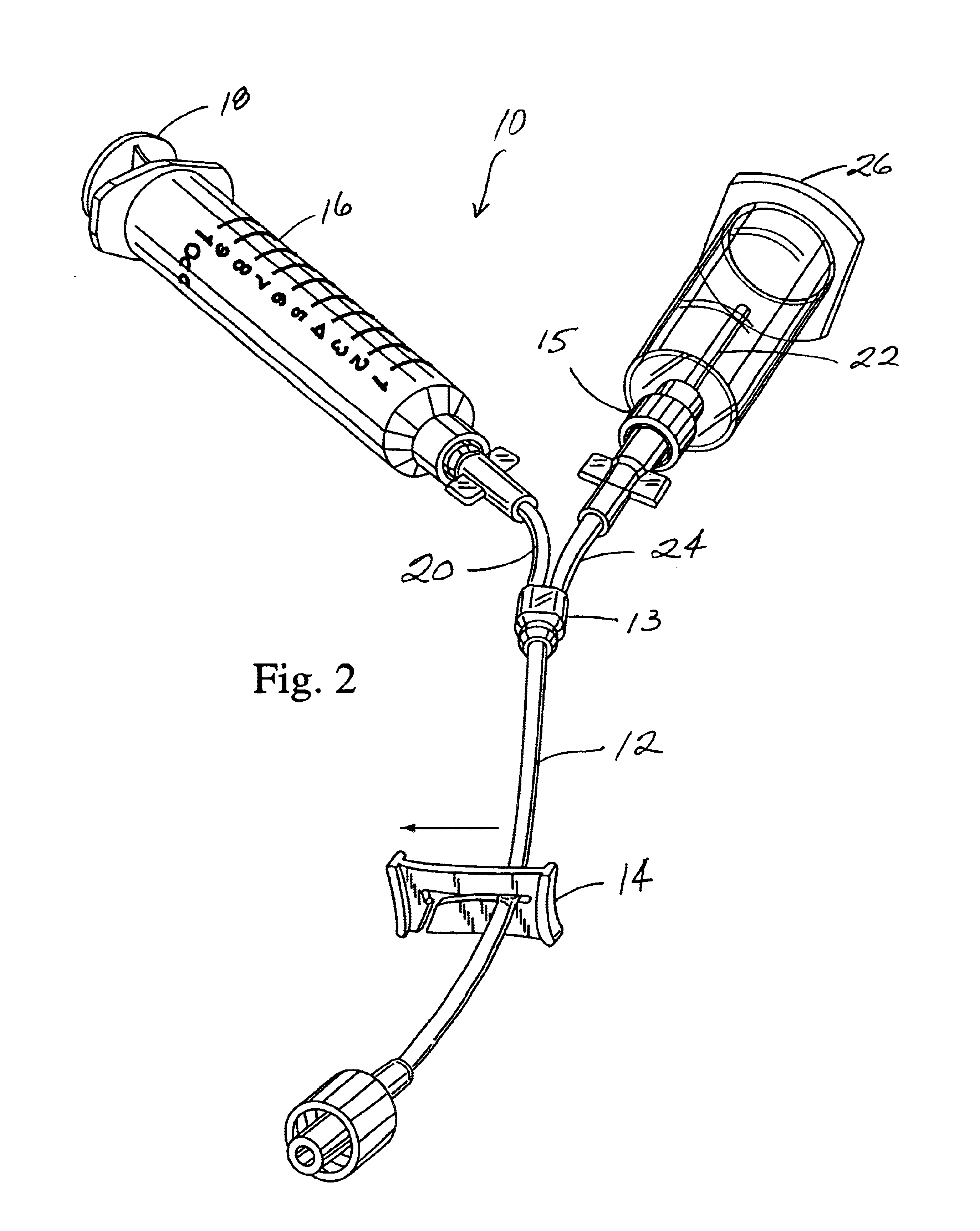
Referring first to FIGS. 1 and 2, a blooddrawing system 10 is shown. The system 10 includes a first conduit 12 through which blood from a blood vessel (not shown) of a patient can flow upon standard needle entry thereto. The needle may be connected to conduit 12 by way of a luer connector 11. The first conduit 12 is provided with a closure member here non-limitedly shown as a sliding clamp 14, with FIG. 1 showing the clamp 14 in an open position and FIG. 2 showing it in a closed position. A standard syringe 16 functions as a first collection vessel for receiving blood, and has a standard exteriorly-operable plunger 18 for controllably applying negative or positive pressure within the syringe 16. A second conduit 20 has a first end thereof in fluid communication with the first conduit 12 via a conduit connector 13 and a second end thereof in fluid communication with the syringe 16. The system 10 includes a hollow-shaft member here non-limitedly exemplified as a hollow needle 22 and a...


PUM


Abstract

A blood drawing system including a closeable first conduit through which drawn blood can flow; a first pressurizeable collection vessel for receiving blood therein; a hollow-shaft member; a second conduit leading from the first conduit to the first collection vessel; and a third conduit leading from the first conduit to the hollow shaft member connectable to a negative-pressure second collection vessel. Closing the first conduit allows blood transfer from the first vessel into the second vessel without exposure to or inclusion of any external devices to accomplish such transfer. Also included is an intravenous system with a conduit through which medicament liquid can be delivered and from which medicament liquid-free blood can be withdrawn. A first pressurizeable vessel first removes and conserves for reintroduction residual medicament liquid from the conduit, while thereafter a second negative-pressure vessel draws subsequent medicament liquid-free blood from the conduit.

Description

CROSS-REFERENCE TO RELATED APPLICATIONS(Not Applicable)STATEMENT RE: FEDERALLY SPONSORED RESEARCH / DEVELOPMENT(Not Applicable)BACKGROUND OF THE INVENTIONThe present invention relates in general to blood drawing systems, and in particular to a blood drawing system which, in one embodiment, permits negative pressure control within a vessel to which blood is drawn for preventing vessel collapse because of excess pressure, and, in a second embodiment, for removing and conserving for re-introduction medicament liquid fed through an intravenous conduit prior to blood withdrawal through the intravenous conduit to a negative-pressure collection vessel.Employment of negative-pressure vessels for collecting blood samples from arterial or venous blood vessels of living beings is a common practice in medical treatments where subsequent laboratory analysis of the blood samples so collected helps in diagnosing and treating illnesses. In those who are relatively healthy, the use of standard negativ...

Claims


Application Information

Patent Timeline
IPC IPC(8): A61B5/15A61M5/14
CPCA61B5/1444A61M2005/1403A61B5/15003A61B5/150236A61B5/150244A61B5/150732A61B5/150755A61B5/150992A61B5/153A61B5/154
Inventor HYUN, DONGCHUL D.
Owner MPS CAPITAL
Learn More