Vehicle tracker including a connector for an upgrade device and related methods

a technology for upgrading devices and trackers, which is applied in the field of vehicle tracking and alerting systems, can solve problems such as difficult installation of units in vehicles, limited space available for accessing and connecting to vehicle wires, and errors in initial installation

Inactive Publication Date: 2005-01-18
OMEGA PATENTS
View PDF68 Cites 44 Cited by
  • Summary
  • Abstract
  • Description
  • Claims
  • Application Information

AI Technical Summary

Benefits of technology

A method aspect of the invention is for adapting a vehicle tracking unit, as briefly described above, to perform at least one vehicle function. The method may include positioning an upgrade connector adjacent the housing and coupling the upgrade connector to the controller, and removably coupling and upgrade device to the upgrade connector for causing the controller to perform the at least one vehicle function.

Problems solved by technology

Accordingly, such units may be difficult to install in a vehicle.
This is especially so since the space available to access and connect to vehicle wires is likely to be restricted.
Accordingly, errors in the initial installation may occur.
Accurate diagnosis of any such errors may be time consuming and add further to the installation costs.
Maintenance of an installed system may also be complicated if each connection must be individually checked and rechecked.
In addition, when connecting conventional vehicle tracking units in a vehicle along with other vehicle devices, such as remote keyless entry devices, alarm systems, etc., installation can be complicated with the numerous connections that are required.
Not only does such an installation of multiple devices require additional labor, but it also increases the chances for incorrect wiring, which in turn may cause damage to either or both devices.
Moreover, this may create a significant power load on the vehicle battery.

Method used


Image

  • Vehicle tracker including a connector for an upgrade device and related methods
  • Vehicle tracker including a connector for an upgrade device and related methods
  • Vehicle tracker including a connector for an upgrade device and related methods

Examples


Embodiment Construction

The present invention will now be described more fully hereinafter with reference to the accompanying drawings in which preferred embodiments of the invention are shown. This invention may, however, be embodied in many different forms and should not be construed as limited to the illustrated embodiments set forth herein. Rather, these embodiments are provided so that this disclosure will be thorough and complete, and will fully convey the scope of the invention to those skilled in the art. Like numbers refer to like elements throughout.

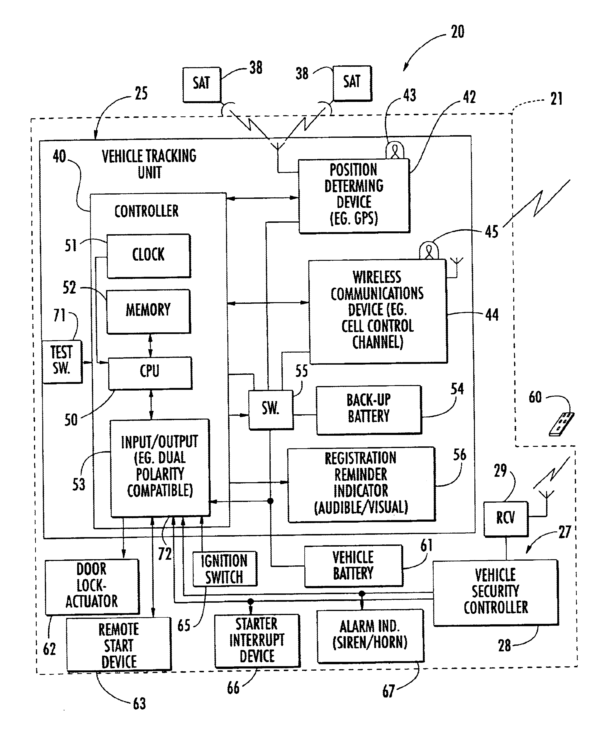
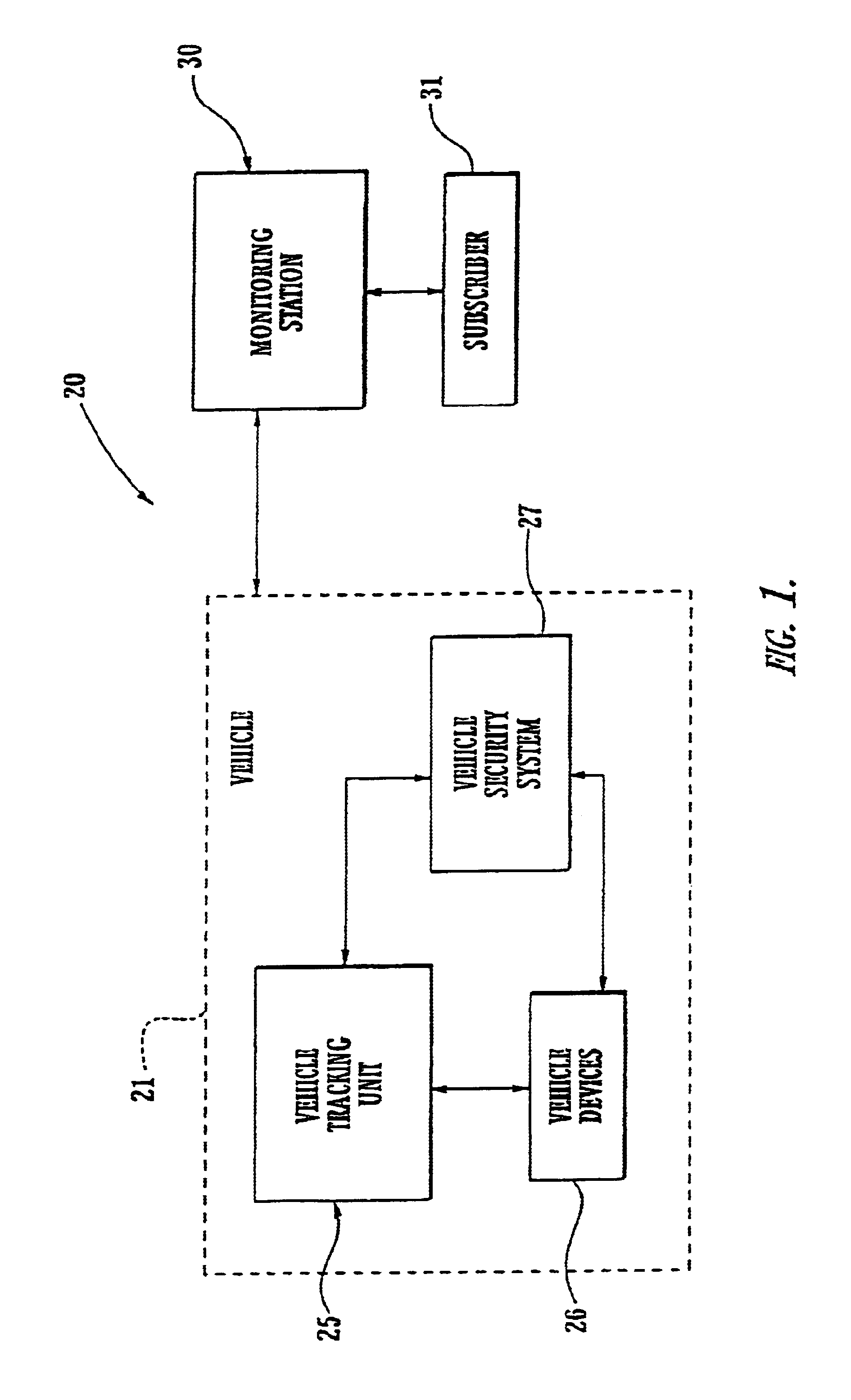
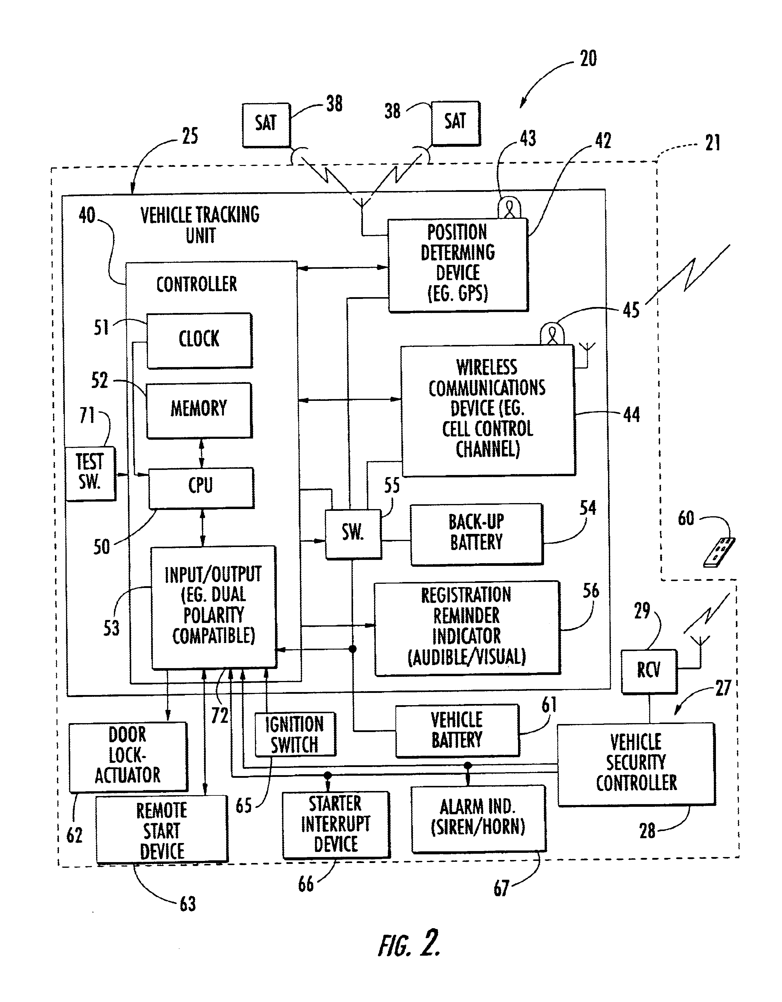
Referring to FIGS. 1-3, the vehicle tracking system 20 in accordance with the invention is now initially described. The vehicle system 20 illustratively includes a vehicle tracking unit 25 to be mounted in the vehicle 21 and a monitoring station 30 which is remote from the vehicle and which is typically in a fixed location. In the illustrated embodiment, the vehicle tracking unit 25 interfaces with various vehicle devices, such as may include security...


PUM


Abstract

A vehicle tracking unit may include a housing, a vehicle position determining device, a wireless communications device, and a controller carried by the housing. The controller may cooperate with the wireless communications device and the vehicle position determining device to determine and send vehicle position information to a monitoring station. Additionally, an upgrade connector may be carried by the housing and coupled to the controller. Also, an upgrade device may be removably coupled to the upgrade connector for causing the controller to perform at least one vehicle function.

Description

FIELD OF THE INVENTIONThe present invention relates to the field of vehicle devices, and, more particularly, to a tracking and alerting system for a vehicle.BACKGROUND OF THE INVENTIONMotor vehicles, such as passenger cars, trucks, busses, fleet vehicles, etc. are widely used and knowing the locations of such vehicles is often desired. For example, should a vehicle be stolen, it would be beneficial to know the vehicle's location so that authorities could be promptly and accurately directed to retrieve the vehicle. Indeed, the tracking system could plot the getaway path of the thief.For a company with hired drivers, it may be desirable to know the driver's whereabouts during the course of the day. Similarly, a rental car agency or other fleet operator, for example, may wish to know the whereabouts of its fleet of vehicles.It may also be desirable to track the location of a vehicle as it is used throughout the course of a normal day. For parents of younger or older drivers, for exampl...

Claims


Application Information

Patent Timeline
Patent Type & Authority Patents(United States)
IPC IPC(8): B60R25/10B60R25/04G07C5/00G08G1/123G01S19/35G01S19/48
CPCB60R25/04B60R25/102B60R25/104B60R25/33G08G1/20G07C5/008B60R2325/205B60W2550/402B60R2325/202B60W2556/50G08G1/205
Inventor FLICK, KENNETH E.
Owner OMEGA PATENTS
Why Eureka
Try Eureka