Diluting system and method

Inactive Publication Date: 2005-01-18
FORCE FLOW
View PDF22 Cites 36 Cited by
  • Summary
  • Abstract
  • Description
  • Claims
  • Application Information

AI Technical Summary

Benefits of technology

We have now discovered that solutions of chemicals such as sodium hypochlorite can be diluted most accurately and reliably with a high degree of automation in common industrial settings when the dilution is based upon the actual weights of chemical

Problems solved by technology

Both of these methods have drawbacks which cannot be solved due to inherent limitations in their technologies.
This method is very inaccurate.
It is adversely affected by variables in the diluent velocity, by any changes in flow cross-section, such as those which occur if there is even the slightest fouling or contamination of the venturi, and by any changes in back pressure in the undiluted chemical feed tank.
This process has the disadvantages of

Method used


Image

  • Diluting system and method
  • Diluting system and method
  • Diluting system and method

Examples


Embodiment Construction

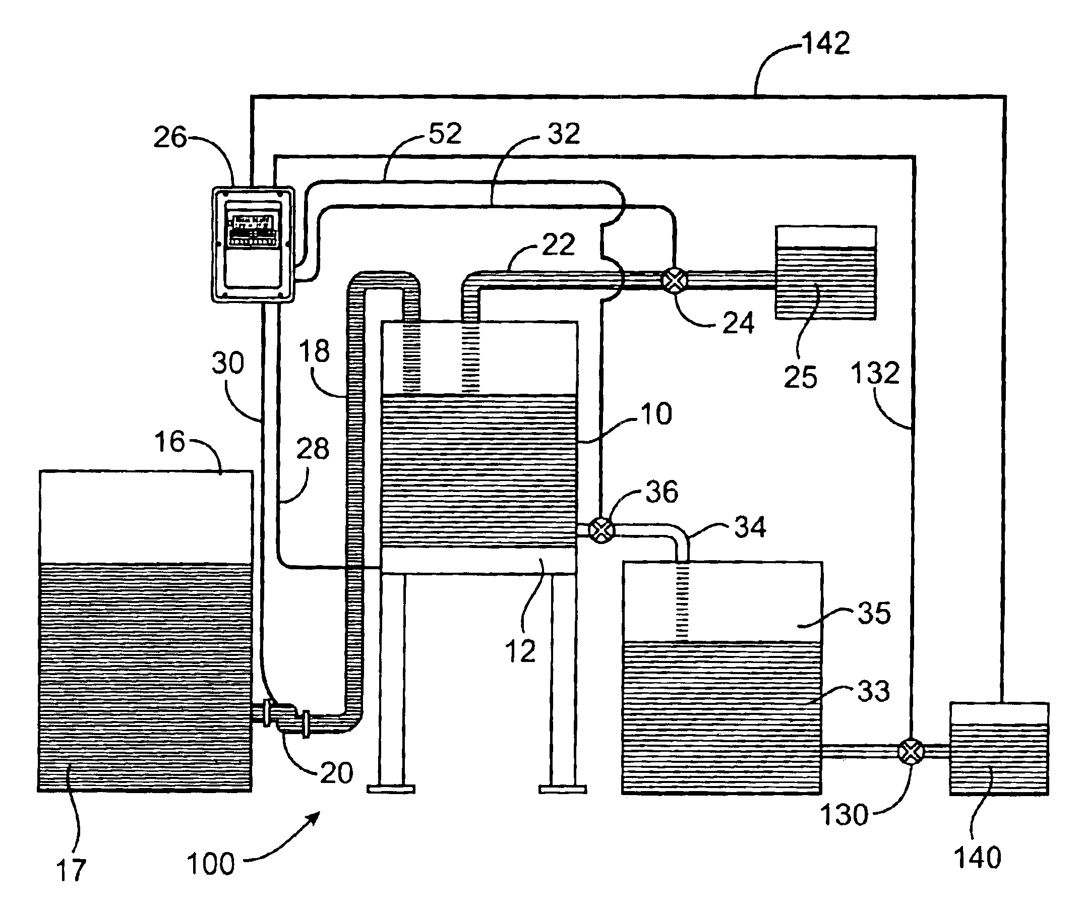
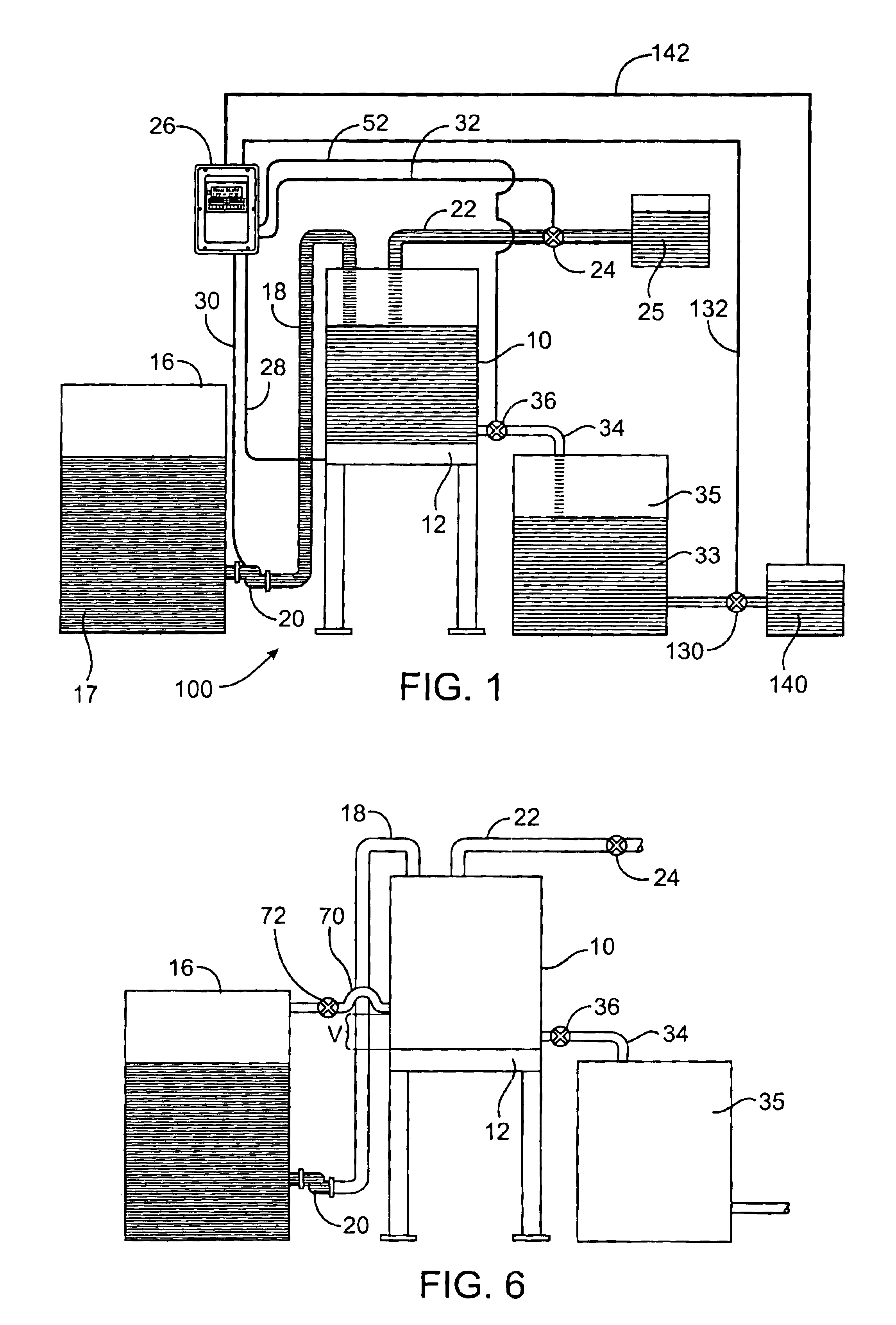
Turning to the drawings, a system 100 for diluting chemicals in accord with this invention is shown in FIG. 1. This system and the method of its use will be described in the context of a sodium hypochlorite concentrate solution as the concentrated chemical and water as the diluent. It will be appreciated that these materials are not limiting and that this system and its use could work with a wide range of chemicals and diluents.

System 100 includes dilution tank 10. The capacity of this tank 10 is known and most commonly is smaller than might typically be selected in a manually-operated setting. This use of a smaller-than-usual dilution tank 10 is advantageous. It permits more frequent adjustments in diluted product concentration as may be needed to deal with changing needs for the diluted chemical. It also allows for a smaller capital investment. Tank 10 is positioned upon scale 12 which can generate signals related to the empty weight, full weight and partially full weight of the d...


PUM

PropertyMeasurementUnit
Weightaaaaaaaaaa
Flow rateaaaaaaaaaa
Concentrationaaaaaaaaaa

Abstract

A system and a method for automatically, accurately diluting chemical solutions on an industrial scale based upon real time weight measurements of chemical and diluent weight is disclosed.

Description

FIELD OF THE INVENTIONThis invention relates to a system for preparing diluted chemical solutions for use in industrial processes. More particularly, it relates to an apparatus and associated controller for preparing and dispensing such solutions and the methods of diluting which they permit.BACKGROUND OF THE INVENTIONTraditionally, diluting chemicals from their neat chemical strengths to something less has been accomplished via a venturi method or by volume via a level probe in a dilution tank. Both of these methods have drawbacks which cannot be solved due to inherent limitations in their technologies.In the case of a typical venturi dilution method, a flow of diluent is passed through a venturi. This flow creates a suction into which predilution material is drawn from a feed tank. The two flows mix in the venturi to form the desired diluted stream. This method is very inaccurate. It is adversely affected by variables in the diluent velocity, by any changes in flow cross-section, ...

Claims


Application Information

Patent Timeline
IPC IPC(8): B01F15/00B01F3/08B01F15/04G05D21/00G05D21/02
CPCB01F3/088B01F15/00123B01F15/00136B01F15/00194G05D21/02B01F15/00344B01F15/0441B01F15/0479B01F15/0022B01F2003/0896B01F23/483B01F23/49B01F35/2111B01F35/2117B01F35/20B01F35/2132B01F35/2211B01F35/88B01F35/883B01F35/21
Inventor NELSON, MARKTOWNSEND, MIKEDAVIDSON, BRAD
Owner FORCE FLOW
Why Eureka
Try Eureka