Metal casting core assembly for casting a crankshaft

a crankshaft and metal casting technology, applied in the direction of manufacturing tools, foundry patterns, moulding apparatus, etc., can solve the problems of adding cost to the casting process, difficulty in maintaining dimensional accuracy in the final cast part, and molding parting lines

Inactive Publication Date: 2005-01-25
FORD MOTOR CO
View PDF6 Cites 19 Cited by
  • Summary
  • Abstract
  • Description
  • Claims
  • Application Information

AI Technical Summary

Benefits of technology

According to another aspect of the invention relating to insert weights, an insert made of a metal composition that has a different mass than the molten metal used to form the crankshaft may be molded into a part of the crankshaft such as the counter-weight. Sand positioning members may be secured between the sand cores and the insert to retain the insert within one of the interior openings prior to filling the core with molten metal.
Other aspects of the invention relate to manufacturing of a crankshaft for an engine. The invention may be applied to 4, 6, 8, 10 or 12 cylinder engine crankshafts. In the illustrated embodiment, a V-6 crankshaft may be made with eleven cores that are arranged along the rotational axis of the crankshaft wherein the first core has an interior opening defining a post end of the crankshaft, a first main bearing and part of a first counter-weight. The second sand core has two sides with an interior opening defining on a first side a first connecting rod pin and a part of a first counter-weight and on a second side thereof a part of the second counter-weight. A third sand core has two sides and an interior opening defining on a first side a fourth connecting rod pin and part of the second counter-weight and on a second side part of a third counter-weight. The fourth sand core defines on a first side a second main bearing journal and part of the third counter-weight and on a second side part of a fourth counter-weight. A fifth sand core has two sides with an interior opening defining

Problems solved by technology

One problem with conventional core boxes and in particular with regard to core boxes for casting crankshafts is that it is difficult to maintain dimensional accuracy in the final cast part.
Another problem with conventional casting processes is that the cast parts generally must be homogeneous as cast and do not permit selectively weighting portions of counter-weights with

Method used


Image

  • Metal casting core assembly for casting a crankshaft
  • Metal casting core assembly for casting a crankshaft
  • Metal casting core assembly for casting a crankshaft

Examples


Embodiment Construction

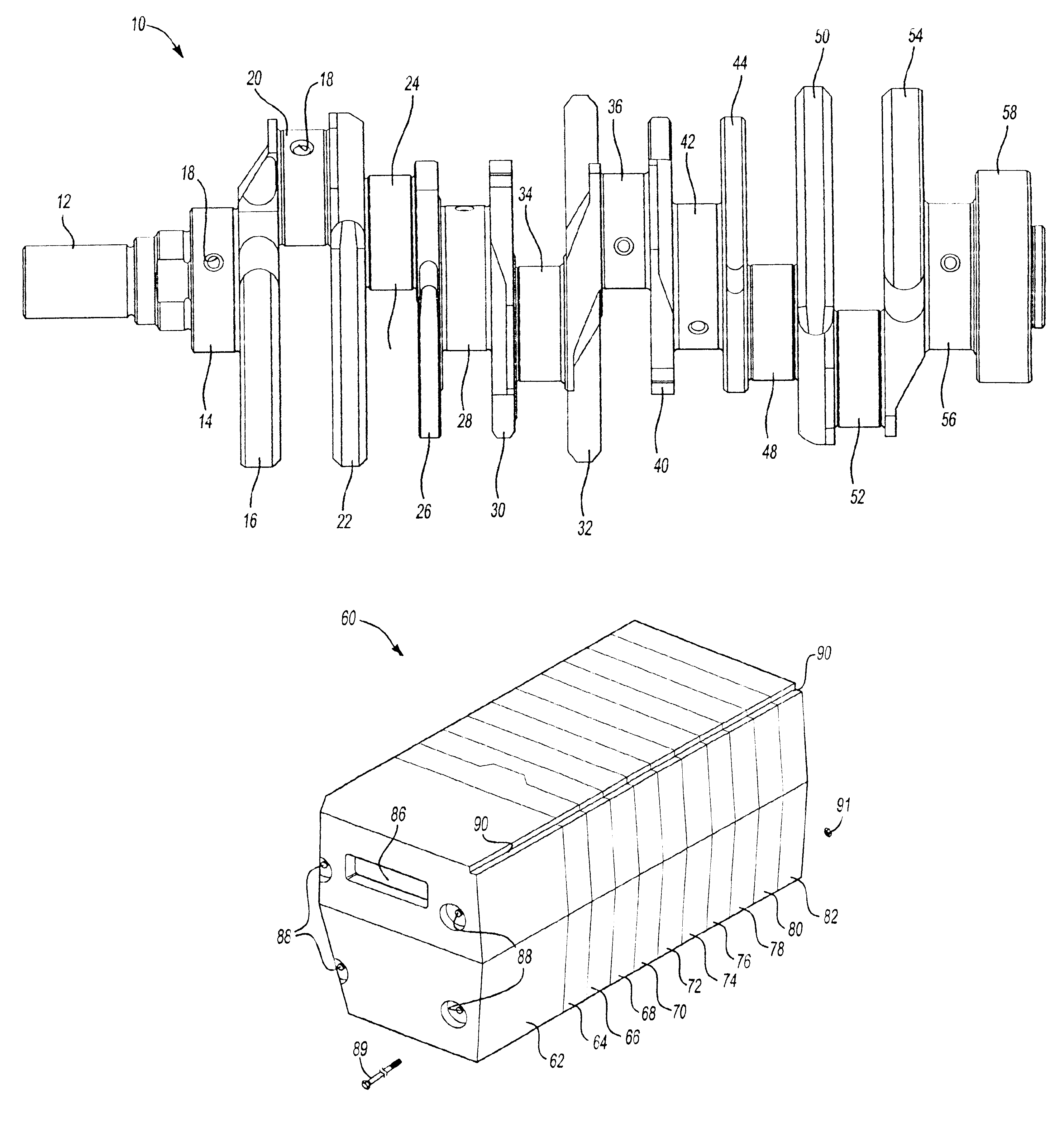
Referring now to FIG. 1, a crankshaft 10 for a V-6 engine that may be made according to the present invention is illustrated. The crankshaft 10 has a post end 12 and first main bearing journal 14 that is adjacent to a first counterweight 16. An oil gallery passage 18 opens into the first main bearing journal 14 and extends to a first connecting rod pin 20. The oil gallery passage 18 distributes oil to bearings at desired locations on the crankshaft 10.

The first connecting rod pin 20 is adapted to receive the end of a piston connecting rod and is disposed between the first counterweight 16 and a second counterweight 22. A fourth connecting rod pin 24 is disposed between the second counterweight 22 and a third counterweight 26. A second main bearing journal 28 is located between the third counterweight 26 and a fourth counterweight 30. A fifth counterweight 32 is provided on the opposite side of a second connecting rod pin 34. The second connecting rod pin 34 is disposed between fourt...


PUM

PropertyMeasurementUnit
Temperatureaaaaaaaaaa

Abstract

A core box assembly for casting a crankshaft. The core box assembly comprises axially aligned cores that define different axial portions of a cavity that receives molten metal to cast the crankshaft. Oil gallery cores are placed in the core box assembly to form as-cast oil galleries in the crankshaft. Heavy metal inserts are held by sand cores disposed in the portions of the cavity that form the counterweights of the crankshaft.

Description

BACKGROUND OF INVENTION1. Field of the InventionThe present invention relates to a sand core assembly for casting metal parts.2. Background ArtMetal casting is a technique that may be used to form complex parts. The parts may be formed from ductile iron, aluminum or other metals. Examples of ductile iron castings include engine crankshafts, valve camshafts, engine blocks and other parts.Conventional core boxes are generally formed with a clamshell design having two halves that are split longitudinally at a parting line. One problem with conventional core boxes and in particular with regard to core boxes for casting crankshafts is that it is difficult to maintain dimensional accuracy in the final cast part. Conventional cast crankshafts require substantial machining to form a flange hub pilot hole, oil gallery passages and shape counter-weights. In conventional core boxes a three degree draft angle is provided on counter-weight cheeks and substantial machining or “cheeking,” is requi...

Claims


Application Information

Patent Timeline
IPC IPC(8): B22C9/00B22C9/10B22C9/12B22C21/14
CPCB22C9/103B22C21/14B22C9/123
Inventor BALTZ, GENE FREDERICZAGORSKI, VICTOR C.
Owner FORD MOTOR CO
Why Eureka
Try Eureka