
Hydrostatic machine

a technology of hydrostatic machine and swivel body, which is applied in the direction of mechanical equipment, engines with rotating cylinders, liquid fuel engines, etc., can solve the problems of increasing the number of components, disadvantageous known design, and impairment of the swivel bearing for the swivel body, so as to improve the service life of the swivel bearing and reduce the number of components. , the effect of simple design

Inactive Publication Date: 2005-01-25
HYDROMATIK GMBH
View PDF13 Cites 3 Cited by
  • Summary
  • Abstract
  • Description
  • Claims
  • Application Information

AI Technical Summary

Benefits of technology

The object on which the invention is based is to simplify a hydrostatic machine of the type specified at the outset, while ensuring a stable construction. Not only is the construction of the one-piece main housing body to be simplified, but also the swivelling bearings for the swivelling body, the intention further being to achieve not only a simple but also a precise production of the swivelling bearings.
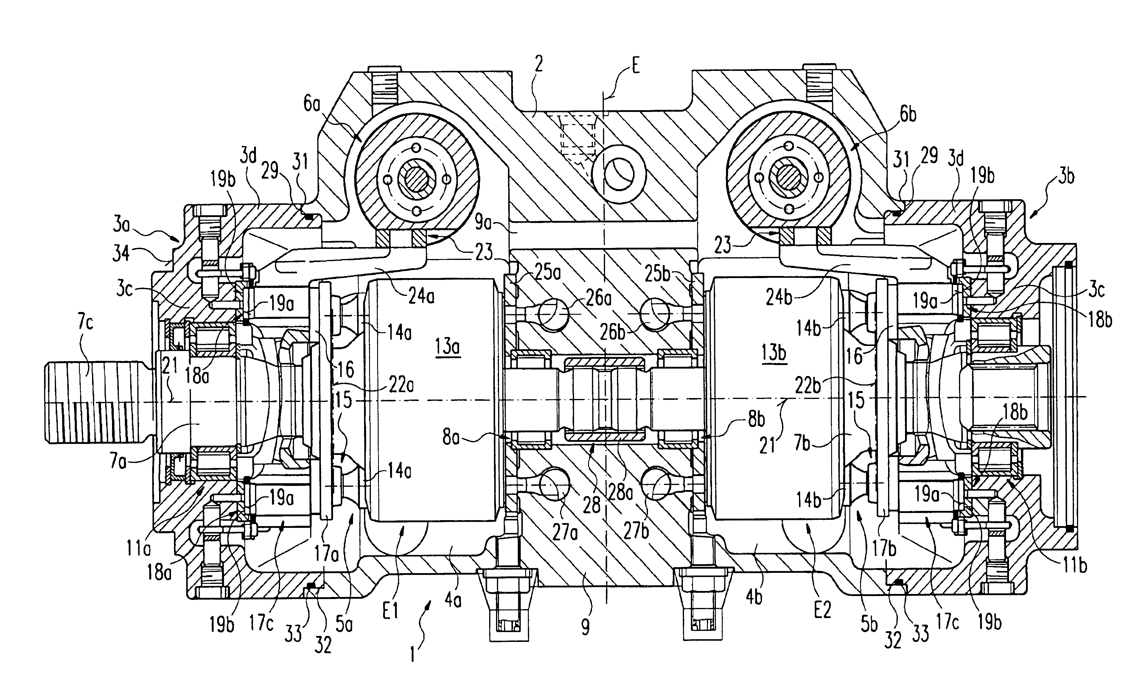
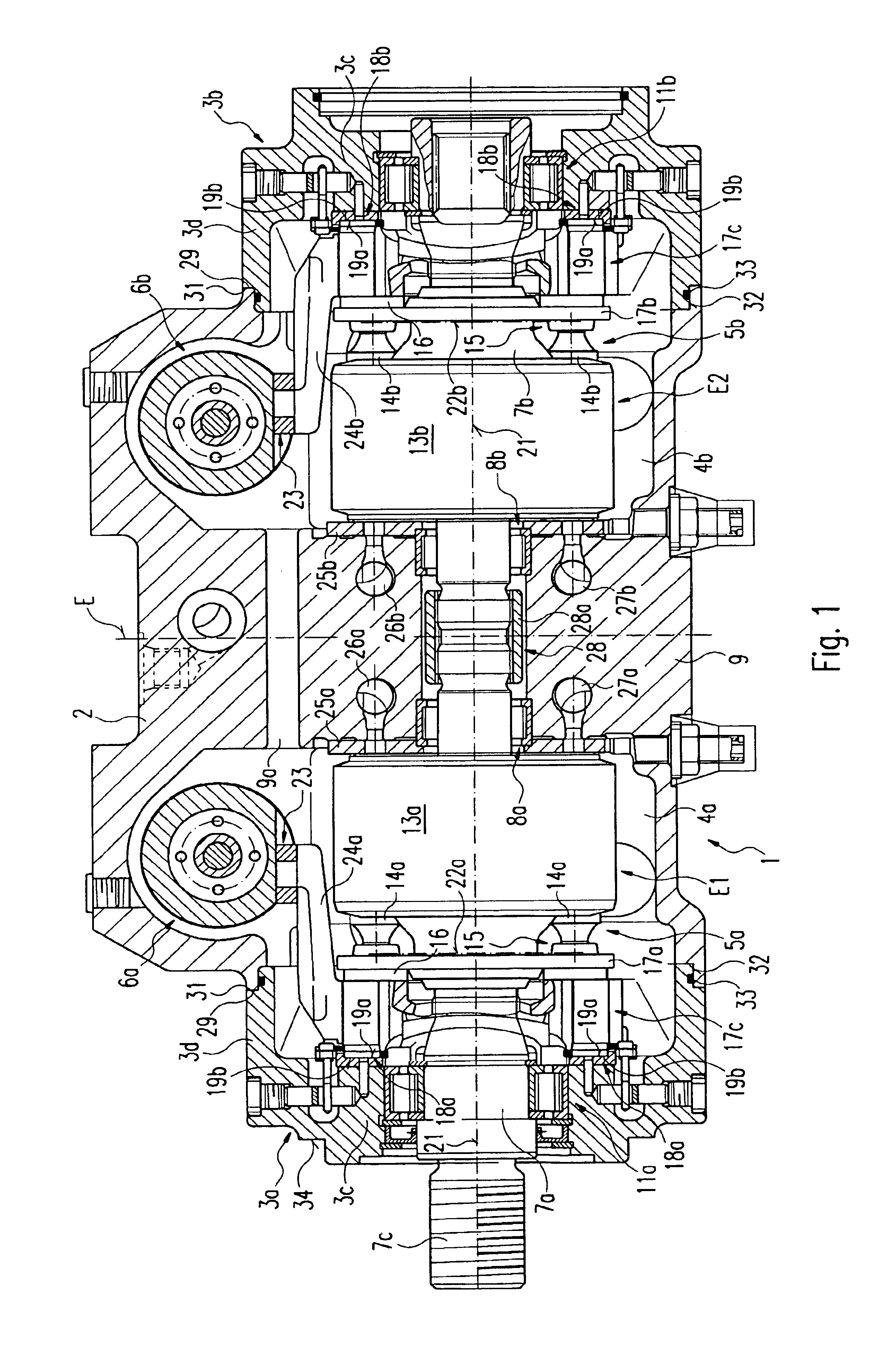
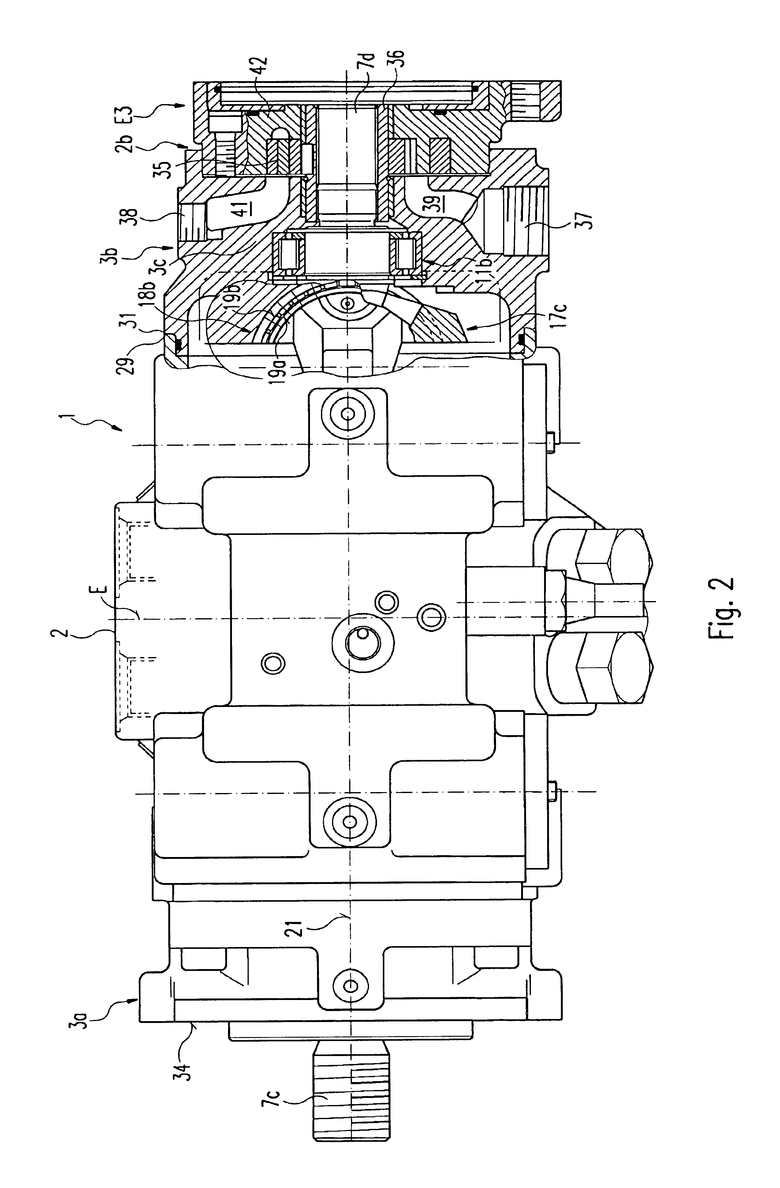
In the hydrostatic machine according to the invention, provision is made for a first add-on housing body which is mounted onto the main housing body and on which the swivelling body of the first hydrostatic unit is mounted, and for a second add-on housing body which adjoins the main housing body and on which the swivelling body of the second hydrostatic unit is mounted. In this case, the first and the second add-on housing body form end-side add-on parts arranged in the region of the end-side housing openings which are required in any case for the passage of the drive shafts and in the region of which the add-on housing bodies can be stably mounted onto the main housing body while ensuring a simple design. In this case, the end-side openings may be designed to be of such a size that the cylinder drums and the swivelling bodies of the first and second hydrostatic unit are each mountable and demountable through the end-side openings. An essential advantage of the design according to the invention is also that the swivelling bearings are each formed on one and the same component, namely on the first and second add-on housing bodies. In this case, the respective bearing surfaces of the swivelling bearings on the add-on housing bodies can each be produced not only in a simple and easily accessible manner but also, when clamped to machining equipment, in a precise manner, as a result of which the bearing quality is improved and the service life of the swivelling bearing is increased. A further advantage of the design according to the invention is that both the swivelling bearing and the bearing for the associated drive shaft are formed on the first and second add-on housing body, as a result of which not only is a compact construction achieved but likewise also a simple and precise production of both bearing formations on respectively one and the same add-on housing body. It is also to be seen as a further advantage of the design according to the invention that the housing of the hydrostatic machine consists of just three components, namely the one-piece main housing body and the two add-on housing bodies.
The add-on housing bodies can also be designed as components which, after associated fastening elements, in particular fastening screws, have been released, are rotatable about the axis of rotation of the associated drive shaft and can be mounted onto the main housing body in different rotational positions. This is particularly advantageous when the hydrostatic units are formed by axial piston machines. In fact, the direction of rotation of the interconnected drive shafts can be determined by mounting on the add-on housing bodies in mounting-on positions rotated through 180°. As a result, the usability of the hydrostatic machine and its adaptation to different operating conditions are improved. A factor which also contributes to this is that, in the design according to the invention, the drive shafts can each form a mounting unit with the associated add-on housing body if both mounting units are designed mirror-symmetrically with respect to a centre plane, extending at right angles to the drive-shaft axes, of the main housing body. Such a design enables the hydrostatic units to be mounted in a manner such that they are rotated through 180° with respect to a transverse axis running in the centre plane. This achieves not only the effect that the output end of the drive-shaft arrangement can be arranged on one side or the other as desired, but it is also possible to determine the direction of rotation of the hydraulic unit in the way described above.
Further features of developments lead to simple, small or compact, and inexpensively producible and assemblable constructions, as a result of which the hydrostatic machine is further improved.

Problems solved by technology

This known design is disadvantageous for several reasons.
First of all, the main housing body is not only of a complicated structural shape due to the additional presence of the transversely directed access openings, but is also considerably weakened by the access openings, so that the main housing body must be stably designed in its remaining structural sections to be able to take the stresses placed upon it in operation.
A further disadvantage is that two additional covering plates have to be provided, as a result of which not only is the number of components increased, but they have also to be mounted and sealed and they contribute to the complicated construction.
A further disadvantage with this is that, owing to scarcely avoidable tolerances, positional differences between the bearing surfaces arranged on the main housing body and the bearing surfaces arranged on the covering plates are to be expected, which leads to impairment of the swivelling bearings for the swivelling bodies, in particular under high stresses, as a result of which the service life of the swivelling bearings and thus also of the hydrostatic machine as a whole can be impaired.

Method used


Image

  • Hydrostatic machine
  • Hydrostatic machine
  • Hydrostatic machine

Examples


Embodiment Construction

The main parts of the hydrostatic machine, denoted as a whole by 1, are a main housing body 2, two add-on housing bodies 3a, 3b mounted onto the main housing body at mutually opposite end sides, two housing chambers 4a, 4b, in each of which is arranged a hydrostatic unit E1, E2, preferably in the form of a piston machine 5a, 5b, the piston machines 5a, 5b each being adjustable with respect to their throughput volume by an adjusting device 6a, 6b. The piston machines 5a, 5b each have a drive shaft 7a, 7b which are arranged coaxially, the drive-shaft ends which face each other being rotatably mounted, by means of bearings 8a, 8b, on a housing centre wall 9 extending between the housing chambers 4a, 4b. The ends, which face away from each other, of the drive shaft 7a, 7b are mounted, by means of rotary bearings 11a, 11b, on the add-on housing bodies 3a, 3b, having through-holes in which the rotary bearings 11a, 11b are arranged. A channel 9a connecting the chambers 4a, 4b is provided i...


PUM


Abstract

The invention relates to a hydrostatic machine (1) comprising at least one first hydrostatic unit (E1) and one second hydrostatic unit (E2), each hydrostatic unit (E1, E2) comprising respective pistons (14a, 14b) guided in respective cylinder drums (13a, 13b) and supported by respective swiveling bodies (17a, 17b) that can be adjusted by respective adjustment devices (6a, 6b), and further comprising respective control bodies (25a, 25b). A one-piece main housing body (2) radially surrounds the cylinder drums (13a, 13b), the control bodies (25a, 25b), and the adjustment devices (6a, 6b) of both hydrostatic units (E1, E2), and assigns pressure channels for supplying a pressure medium to and discharging it from the control bodies (25a, 25b) of both hydrostatic units (E1, E2). A first add-on housing body (3a) is disposed on a first side of the main housing body (2), and bears a swiveling body (17a) of the first hydrostatic unit (E1). On a second side of the main housing body (2) a second add-on housing body (3b) is provided which bears the swiveling body (17) of the second hydrostatic unit (E2).

Description

BACKGROUND OF THE INVENTIONThe invention relates to a hydrostatic machine according to the precharacterising clause of claim 1.A hydrostatic machine of this type is described in DE 195 12 993 A1.This known hydrostatic machine is a so-called double-pump unit with a one-piece main housing body having a centrally arranged housing centre wall and on each side a housing end wall, respective housing chambers being arranged between the housing centre wall and the housing end walls, in which housing chambers respective cylinder drums with pistons guided therein such that they can be displaced substantially axially to and fro are arranged, which pistons are supported on a swivelling body likewise arranged in the housing chamber. The cylinder drums are mounted on respective drive shafts which internally are rotatably mounted in bearing bores of the housing centre wall and externally pass through the associated housing end wall in a bearing hole and are likewise rotatably mounted therein. Each...

Claims


Application Information

Patent Timeline
Patent Type & Authority Patents(United States)
IPC IPC(8): F04B1/12F04B1/16F04B1/22F04B53/00
CPCF04B1/16
Inventor WANSCHURA, GUENTHERSCHNIEDERJAN, REINHOLDGINTNER, JURGEN
Owner HYDROMATIK GMBH
Learn More