Series drive clutch

Inactive Publication Date: 2005-01-25
NTN CORP
View PDF14 Cites 142 Cited by
  • Summary
  • Abstract
  • Description
  • Claims
  • Application Information

AI Technical Summary

Benefits of technology

The present invention addresses these requirements by providing an electrically actuated bi-directional roller clutch that is connected to the vehicle's electric motor-generator and engine. The electrically actuated bi-directional roller clutch is installed on the output shaft of the electric motor-generator and mated to a planetary gearset in such a manner that the output of the planetary gearset may vary between direct drive and some other predetermined ratio. A one-way c...

Problems solved by technology

Further, when the vehicle is id...

Method used


Image

  • Series drive clutch
  • Series drive clutch
  • Series drive clutch

Examples


first embodiment

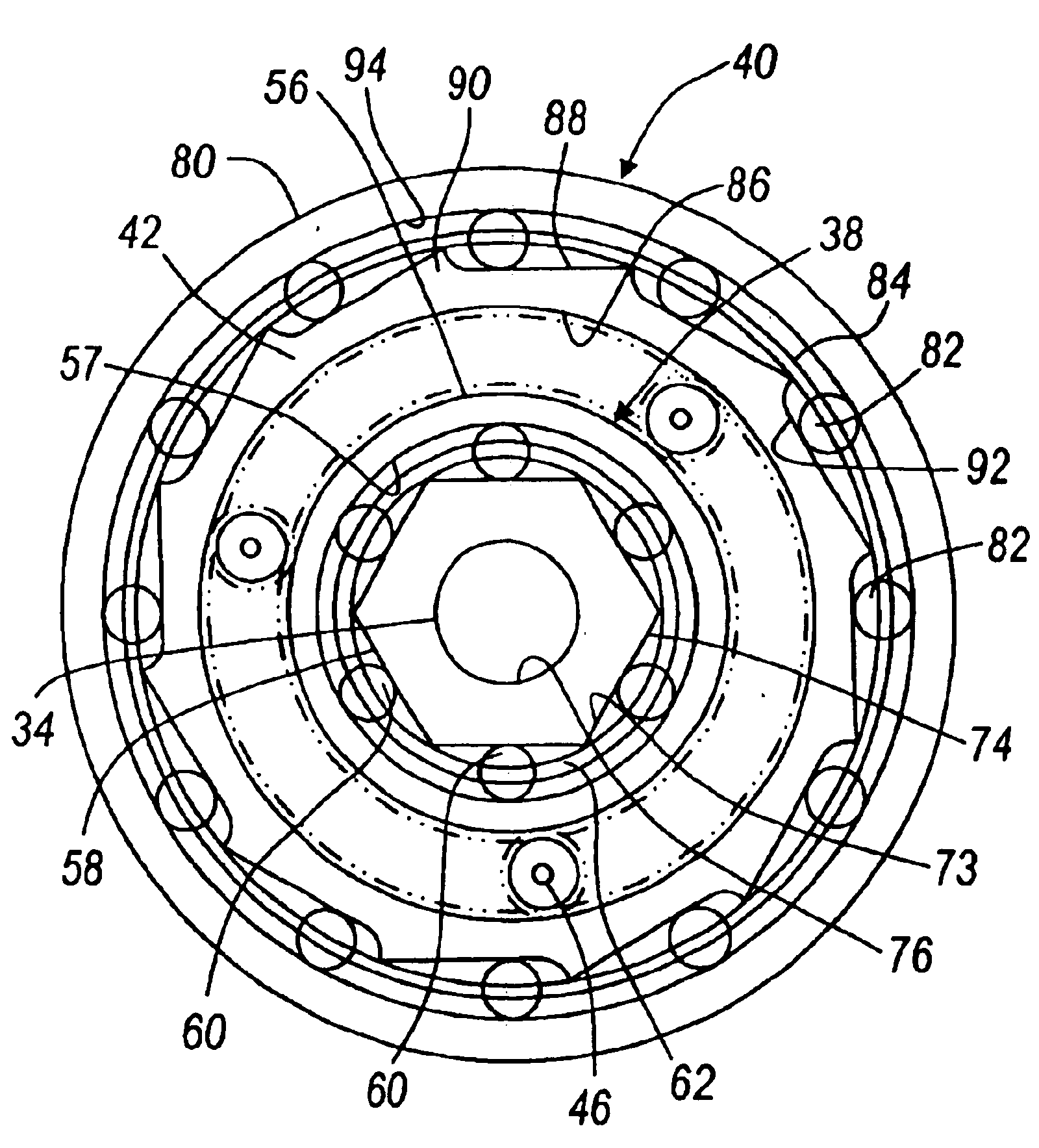
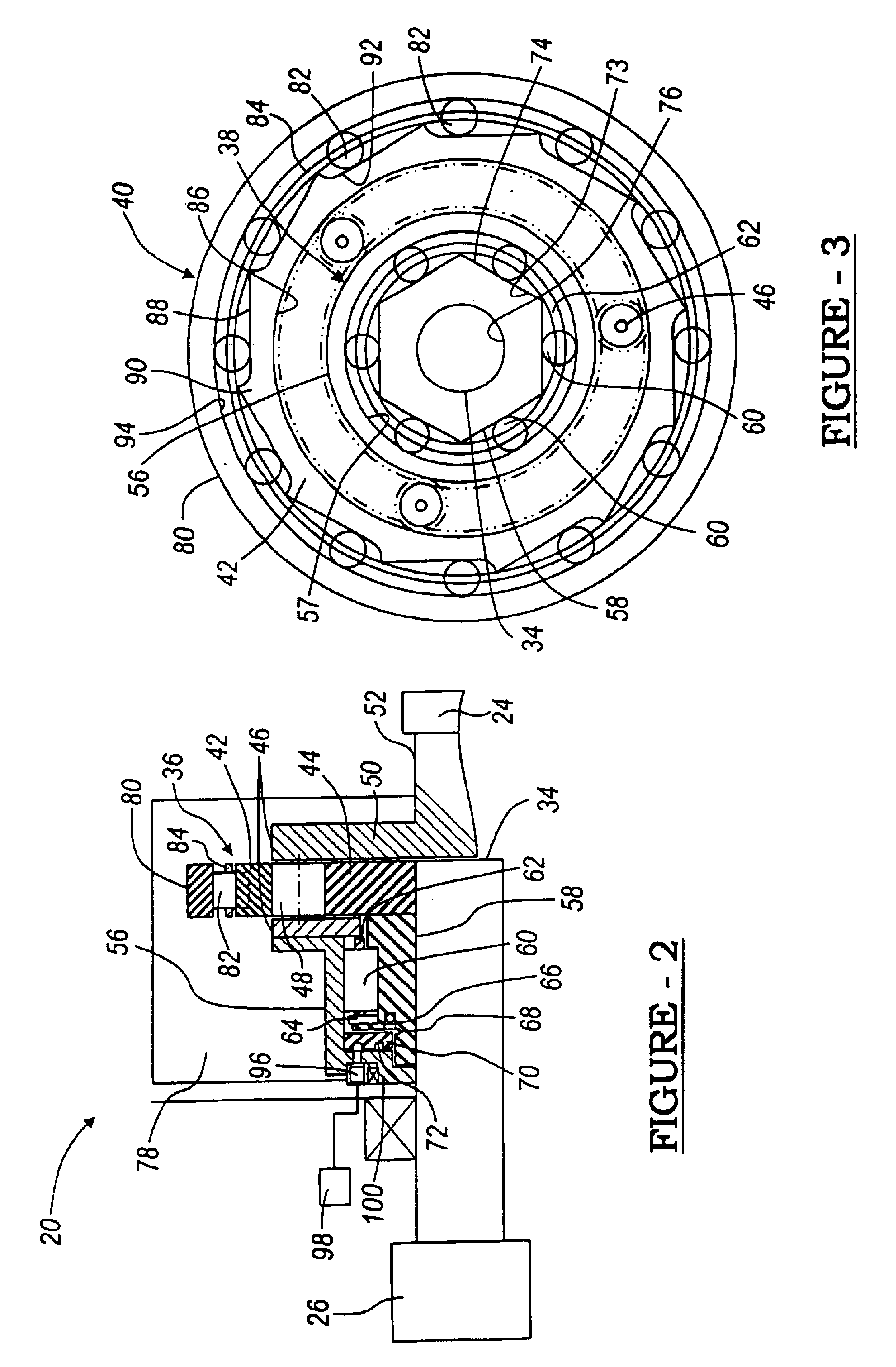
FIGS. 2 and 3 illustrate the first embodiment in which the clutch mechanism 20 includes a bi-directional roller clutch 38, a planetary gearset 36 mated to the bi-directional roller clutch 38, and a one-way clutch 40 integrated into the ring gear 42 in the planetary gearset 36. More specifically, the bi-directional roller clutch 38 links or acts between the sun gear 44 and the planet carrier 46.

The planetary gearset 36 includes a sun gear 44, at least two planet gears 48, a planet carrier 46 and a ring gear 42. Preferably, there are three (3) planet gears 48. The sun gear 44 is connected to the output shaft 34 of the electric motor / generator 26. Each planet gear 48 is in contact with the ring gear 42 and the sun gear 44. The planet carrier 46 is attached to each of the planet gears 48 and links them all together. The planet carrier 46 is also in communication with the engine 24 via attachment to the engine's output shaft or crankshaft 52. The planetary gearset 36 may include an outpu...

third embodiment

In the third embodiment, shown in FIGS. 6 and 7, the bi-directional roller clutch 238 links or acts between the planet carrier 46 and the ring gear 42. The output of the electric motor / generator 34 is connected to the sun gear 44. The inner race 258 is supported by bearings 259 and is connected to the carrier 46. The carrier 46 is connected to the engine's driveshaft 52. The ring gear 42 is connected to the grounded one-way clutch 40 and also to the bi-directional clutch's outer race 256.

As mentioned previously, the engine 24 can drive the electric motor 26 when the clutch mechanism 20, 120, 220 is disengaged for all three embodiments. In this operating mode the power could flow in both directions. Specifically, the output from the engine 24 drives the electric motor 26 through the clutch mechanism 20, 120, 220 resulting in a speed increase. Preferably the speed increase is the inverse of the predetermined gear ratio or 3:1 (three to one). In other words, the electric motor 26 is ro...


PUM


Abstract

A clutch mechanism is disclosed for use with a hybrid electric vehicle wherein the electric motor-generator and engine are arranged in a series configuration. The clutch mechanism is positioned between and in communication with the electric motor-generator and engine to allow for either direct drive or a predetermined gear ratio between the electric motor-generator and engine. The electric motor-generator is preferably an integrated electric motor and generator. The engine is preferably a combustion engine.

Description

BACKGROUND OF THE INVENTIONHybrid electric vehicles (“HEV”) are known to include two power sources to drive the vehicle. It is known to use an electric motor in combination with a combustion engine. In a so-called parallel hybrid system, the two power sources either operate individually or simultaneously. Therefore, there is a need for a mechanism to be positioned between the two power sources to allow for either or both power sources to drive the vehicle.Further, when the vehicle is idling there are competing requirements. The first is to provide minimum power output from the engine to reduce fuel consumption and emissions from the vehicle. On the other hand, the second is to provide enough power for desired vehicle accessories. For instance, the heater, rear defroster and radio may all be on while the vehicle is idling.BRIEF SUMMARY OF THE INVENTIONThe present invention addresses these requirements by providing an electrically actuated bi-directional roller clutch that is connecte...

Claims


Application Information

Patent Timeline
IPC IPC(8): B60K6/04B60K6/00F16D41/08F16D41/00B60K3/02B60K3/04B60K6/365B60K6/383B60K6/387B60K6/48F16D15/00F16D27/10
CPCB60K6/365B60K6/383B60K6/387B60K6/48F16D41/088Y02T10/6221Y10S903/913Y10S903/951Y10S903/905Y10S903/91Y10S903/914Y10S903/917Y02T10/76Y02T10/62
Inventor BAKER, RICHARD D.MONAHAN, RUSSELL E.JACOBSON, RICHARD
Owner NTN CORP
Why Eureka
Try Eureka