Photomultiplier tube

a technology of multi-layer tubes and tubes, applied in the field of photomulti-layer tubes, to achieve the effect of increasing the vibration resistance of the other long sid

Inactive Publication Date: 2005-01-25
HAMAMATSU PHOTONICS KK
View PDF5 Cites 2 Cited by
  • Summary
  • Abstract
  • Description
  • Claims
  • Application Information

AI Technical Summary

Benefits of technology

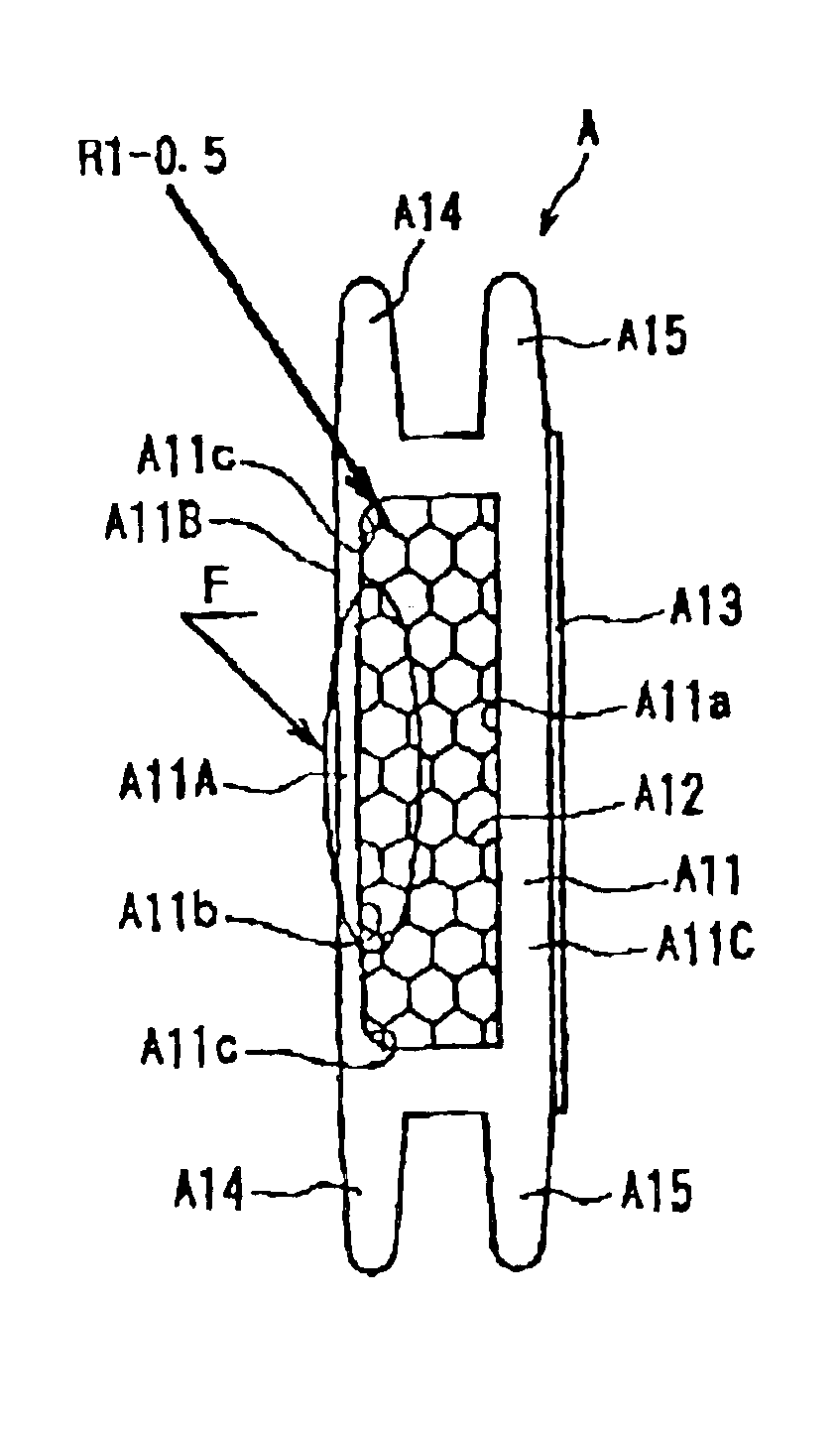
With this construction, the anode wall provided lengthwise along the other long side, which is thicker than the first long side, can increase the vibration resistance of the other long side.
In the photomultiplier tube of the present invention, it is possible to provide a shielding plate between the dynode of the first stage and the dynodes of the (n−3)th through nth stages.
This construction can prevent light and ions generated when electrons collide with dynodes of the (n−3)th through nth stages from traveling toward the photocathode.

Problems solved by technology

However, all of the mesh anodes in the photomultiplier tube of the first through fourth embodiments did not incur damage during the time prescribed for the experiment, exhibiting sufficient vibration resistance for use as a product.

Method used


Image

  • Photomultiplier tube
  • Photomultiplier tube
  • Photomultiplier tube

Examples


Embodiment Construction

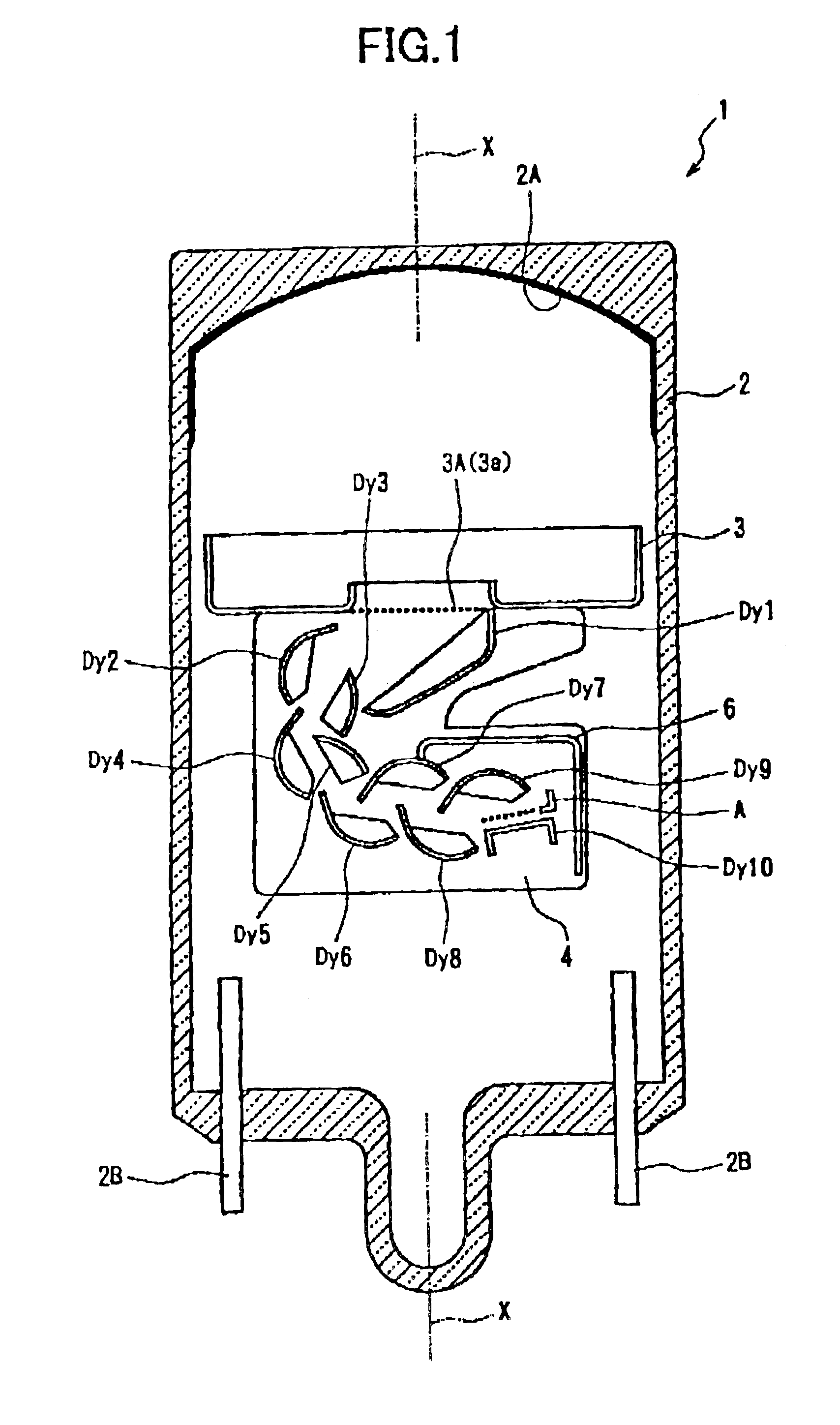
A photomultiplier tube according to a first embodiment of the present invention will be described while referring to FIGS. 1-6. A photomultiplier tube 1 according to the first embodiment includes a tube-shaped vacuum vessel 2 having a tube axis X. FIG. 1 is a cross-sectional view of the photomultiplier tube 1 cut along the tube axis X. The tube-shaped vacuum vessel 2 is formed of Kovar glass or a like material.

Both ends of the tube-shaped vacuum vessel 2 along the tube axis X are closed. One end has a planar shape. A photocathode 2A is formed on the inner surface of this planar end for emitting electrons in response to incident light. The photocathode 2A is formed by reacting an alkali metal vapor with antimony that has been pre-deposited on the inner surface of the end. A plurality of lead pins 2B are provided on the other end of the tube-shaped vacuum vessel 2 for applying prescribed potentials to dynodes Dy1-Dy10 and an anode A. FIG. 1 shows only two of the lead pins 2B for conve...


PUM


Abstract

A photomultiplier tube excellent in vibration resistance and having an anode with good pulse linearity characteristic. The photomultiplier tube has a mesh anode (A) composed of an anode frame (A11) and a mesh electrode (A12) supported and surrounded by the anode frame (A11). The central portion of one long side (A11B) of the anode frame (A11) serves as an electron converging part (F). The inner side of the anode frame (A11) swells toward the inner part of the anode (A), more from the middle of the long side (A11B) toward the corners of the anode frame (A11) along the long side (A11B), and therefore the thickness of the anode frame (A11) increases from the middle of the long side (A11) to the corners along the long side (A11B).

Description

TECHNICAL FIELDThe present invention relates to a photomultiplier tube, and particularly to a photomultiplier tube used in oil exploration and the like.BACKGROUND ARTA type of photomultiplier tube with a shortened axial dimension that has a pole-shaped anode and circular gauge dynodes is well known in the art for use in devices employed in oil exploration or in other devices that vibrate severely.Japanese unexamined patent application publication No. HEI-2-291655 discloses a photomultiplier tube having a circular gauge type electron multiplying unit and a pole-shaped anode. In the circular gauge type electron multiplying unit, a path formed in the spaces between opposed dynodes traces an arc around an axis orthogonal to the tube axis. The dynode of the second stage and the anode are positioned on opposing ends relative to the tube axis. Accordingly, the photomultiplier tube can be contracted in its axial direction, reducing the overall size of the tube construction.In order to form ...

Claims


Application Information

Patent Timeline
Patent Type & Authority Patents(United States)
IPC IPC(8): H01J43/00H01J43/12H01J43/20
CPCH01J43/12
Inventor ISHIZU, TOMOHIROKIMURA, SUENORI
Owner HAMAMATSU PHOTONICS KK
Why Eureka
Try Eureka