Silicon capacitive microphone

a capacitive microphone and silicon technology, applied in the direction of electrical transducers, transducer types, semiconductor electrostatic transducers, etc., can solve the problems of reducing performance, reducing the sensitivity of silicon microphones, and reducing the size of fully clamped diaphragms, so as to reduce the parasitic capacitance, reduce the size of the die, and increase the sensitivity

Inactive Publication Date: 2005-01-25
KNOWLES ELECTRONICS INC
View PDF14 Cites 156 Cited by
  • Summary
  • Abstract
  • Description
  • Claims
  • Application Information

AI Technical Summary

Problems solved by technology

The cost of a silicon microphone is proportional to the product of its complexity, i.e. number of mask steps, and its size.
Fully clamped diaphragms are very stiff for their size.
The second portion is related to the construction of the microphone and is undesirable as it degrades performance.

Method used


Image

  • Silicon capacitive microphone
  • Silicon capacitive microphone
  • Silicon capacitive microphone

Examples


Embodiment Construction

While this invention is susceptible of embodiment in many different forms, there is shown in the drawings and will herein be described in detail a preferred embodiment of the invention with the understanding that the present disclosure is to be considered as an exemplification of the principles of the invention and is not intended to limit the broad aspect of the invention to the embodiment illustrated.

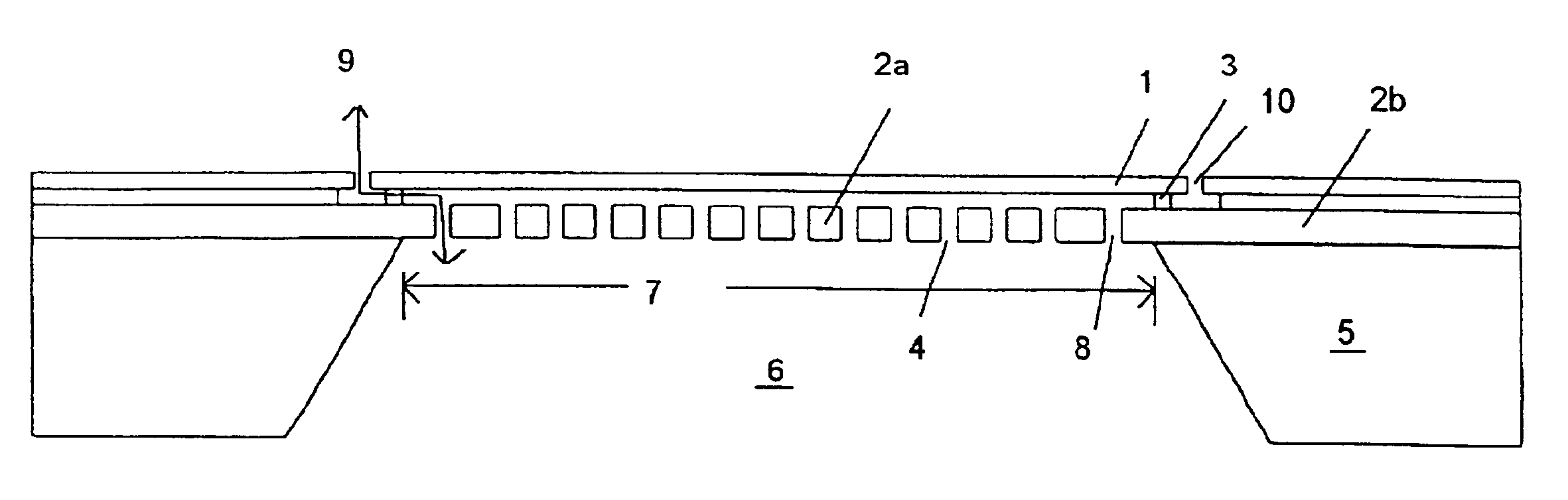
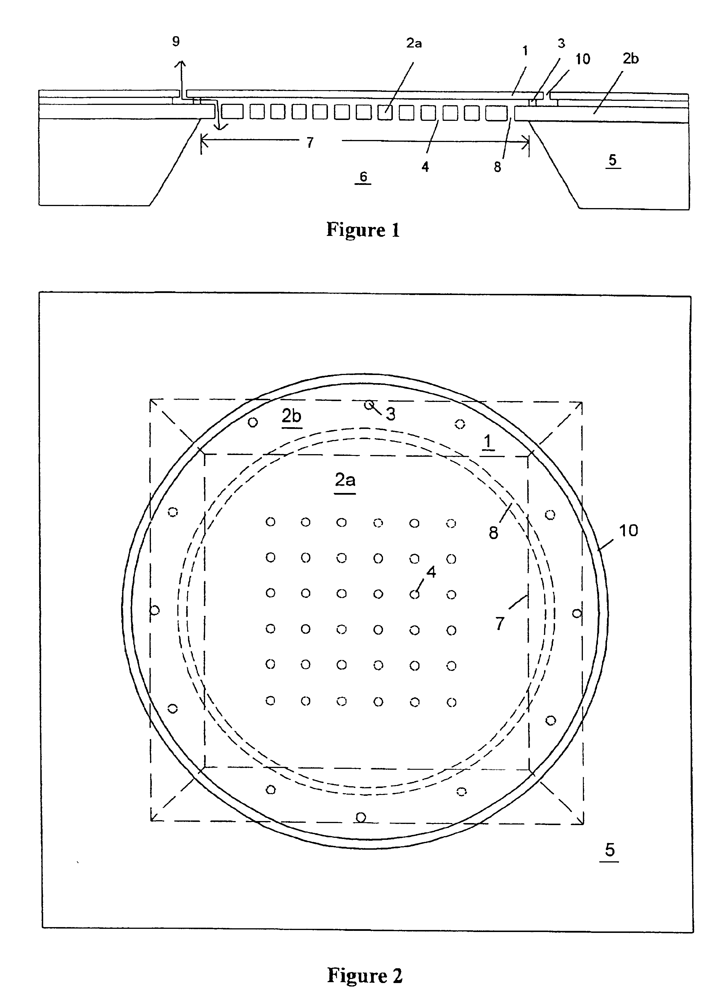
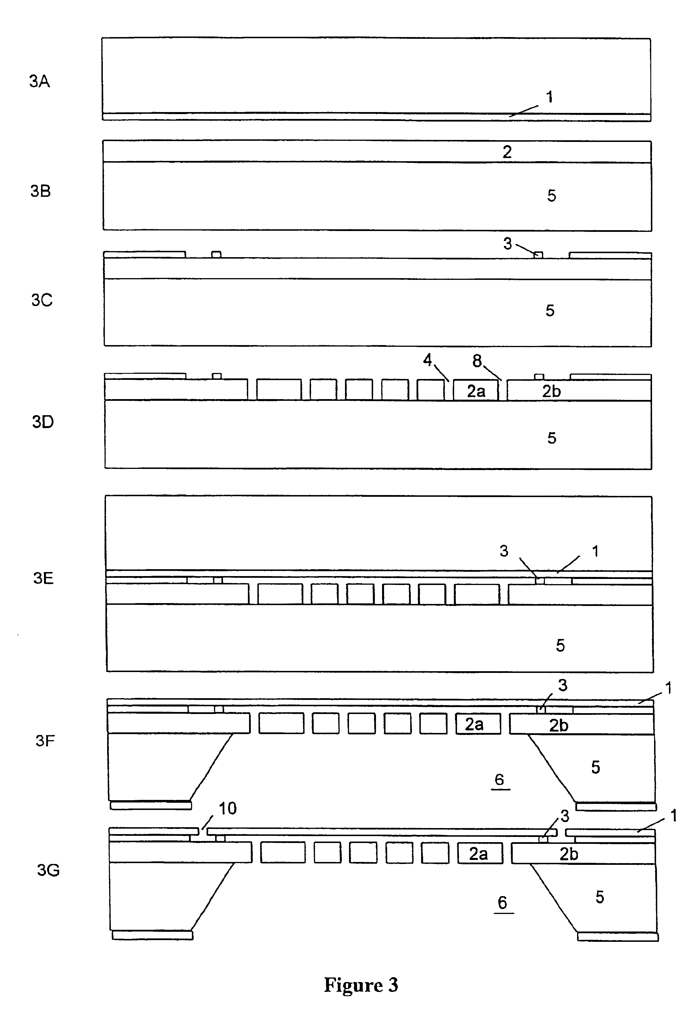
A capacitive microphone is shown in FIG. 1, and comprises a flexible diaphragm 1 supported in close proximity to a rigid backplate 3. The diaphragm 1 of the present invention is supported at its edge by a small number of very small posts or supports 3. The supports 3 allow most, if not all, of the edge of the diaphragm 1 to rotate or flex as acoustic pressure is applied. The rotation or flex of the diaphragm 1 at the edge of the diaphragm 1 lowers the stiffness of the diaphragm 1 when compared to a fully constrained or clamped diaphragm. The posts or supports 3 are connected to a back...


PUM


Abstract

The present invention is directed to a process for the manufacture of a plurality of integrated capacitive transducers. The process comprises the steps of supplying a first substrate of a semiconductor material having first and second faces, supplying a second substrate of a semiconductor material having first and second faces, forming a diaphragm layer on the first face of the first substrate, forming a backplate layer on the first face of the other of the second substrate, forming a support layer on the backplate layer, etching a plurality of supports from the support layer, for each of the capacitive transducers, etching a plurality of vents from the backplate layer, for each of the capacitive transducers, positioning the diaphragm layer of the first substrate adjacent with the support layer of the second substrate, and welding the diaphragm layer and the support layer together, removing at least a portion of the first substrate to expose the diaphragm layer, for each of the capacitive transducers, removing a portion of the second substrate to expose the vents, for each of the capacitive transducers, and, etching a portion of the diaphragm layer, for each of the capacitive transducers.

Description

TECHNICAL FIELDThe present invention relates to a process for manufacturing a silicon based capacitive transducer, such as a microphone. Specifically, the present invention is directed to improving at least issues of size, cost, diaphragm compliance, stray capacitance, and low frequency response control of capacitive transducers.BACKGROUND OF THE INVENTIONConventional electret condenser microphones (ECMs) are widely available and used in significant volumes in numerous consumer products including toys, hearing aids, and cell phones. Replacing the traditional ECM with batch processed silicon microphones is based on meeting or exceeding the performance and cost of the ECM in high volume. The cost of a silicon microphone is proportional to the product of its complexity, i.e. number of mask steps, and its size. In order to scale down a microphone to very small size, a number of different design and process issues must be mastered.U.S. Pat. No. 5,408,731 to Berggvist et al. shows one way...

Claims


Application Information

Patent Timeline
Patent Type & Authority Patents(United States)
IPC IPC(8): H04R19/04H04R19/00
CPCH04R19/04H04R19/005
Inventor LOEPPERT, PETER V.
Owner KNOWLES ELECTRONICS INC
Why Eureka
Try Eureka