Electromagnetic transponder reader

a transponder reader and electromagnetic technology, applied in the field of electromagnetic transponder systems, can solve the problems of adversely affecting the transponder remote supply, the frequency response of the phase demodulator, and the tolerance of capacitors, so as to achieve the effect of reducing the range of capacitors, reducing the cost of capacitors, and improving the reliability

Inactive Publication Date: 2005-01-25
STMICROELECTRONICS SRL
View PDF6 Cites 6 Cited by
  • Summary
  • Abstract
  • Description
  • Claims
  • Application Information

AI Technical Summary

Benefits of technology

The present invention also aims at providing a solution which gets rid of possible manufacturing dispersions of the oscillating circuits of the terminal and / or of the transponders.
To achieve these and other objects, the present invention provides a circuit for demodulating a signal transmitted by an electromagnetic transponder, comprising a sensor of a variable which is a function of the load formed by the transponder on an oscillating circuit, a phase demodulator and an amplitude demodulator at least functionally in parallel and receiving a signal coming from said sensor, a summer of the results provided by said demodulators, and a delay element in series with a first one of said demodulators, to compensate for a possible propagation time difference therebetween.

Problems solved by technology

A problem which arises with conventional read / write terminals using a phase demodulator is that the frequency response of the phase demodulator exhibits, when two oscillating circuits are tuned on the remote supply frequency (13.56 MHz), a zero (that is, the output voltage becomes zero) at a frequency of the signal to be demodulated corresponding to this remote supply frequency.
However, a disadvantage resulting therefrom is that this adversely affects the transponder remote supply, and thus the system range.
Another problem is that the manufacturing tolerances of the capacitors used for oscillating circuits, in particular for capacitor C2 of the transponder, generally are on the order of 10%.
Thus, a significant disadvantage of conventional systems is that a compromise must be made between the remote supply and the phase demodulation capacity of the terminal.
Further, this compromise is difficult to find since the position of the “gap” in the phase demodulator response varies according to the mutual inductance between oscillating circuits.
The combined problems of the phase gap in phase demodulators and of the variation of the position of this phase gap with respect to the distance between inductances, associated with the component manufacturing tolerances, make conventional systems unreliable.
However, this solution only transposes the problem since the spectral response of an amplitude demodulator also exhibits a demodulation gap, that is, a frequency for which the voltage obtained at the demodulator output is zero.
The significant variation of the resonance frequencies of oscillating circuits due to the capacitor manufacturing tolerances, associated with the significant variation of the position of the demodulation gap according to the coupling between oscillating circuits results in that, in practice, the use of an amplitude demodulator risks posing substantially the same problems as the use of a phase demodulator.
However, the solution described in this document is not fully satisfactory.
Indeed, it does not enable, in practice, modifying the choice between the phase demodulation and the amplitude demodulation, upon reception, since the signals demodulated by the two demodulators are not necessarily synchronous.
Further, the disadvantages linked to the manufacturing tolerances of oscillating circuits and their operation drift remain.

Method used


Image

  • Electromagnetic transponder reader
  • Electromagnetic transponder reader
  • Electromagnetic transponder reader

Examples


Embodiment Construction

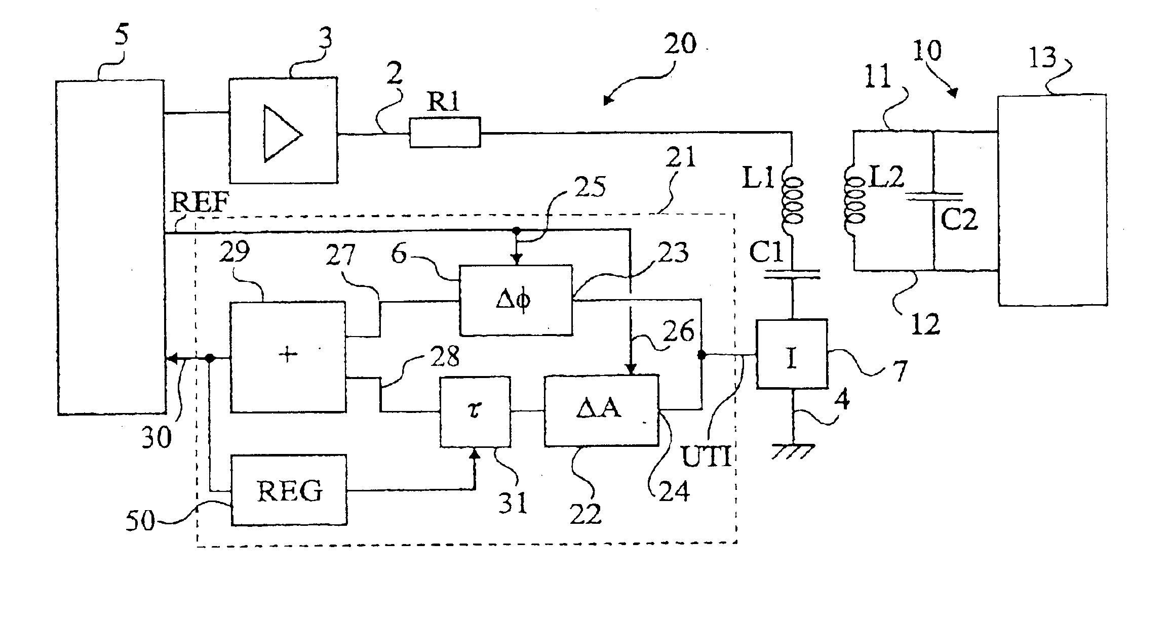
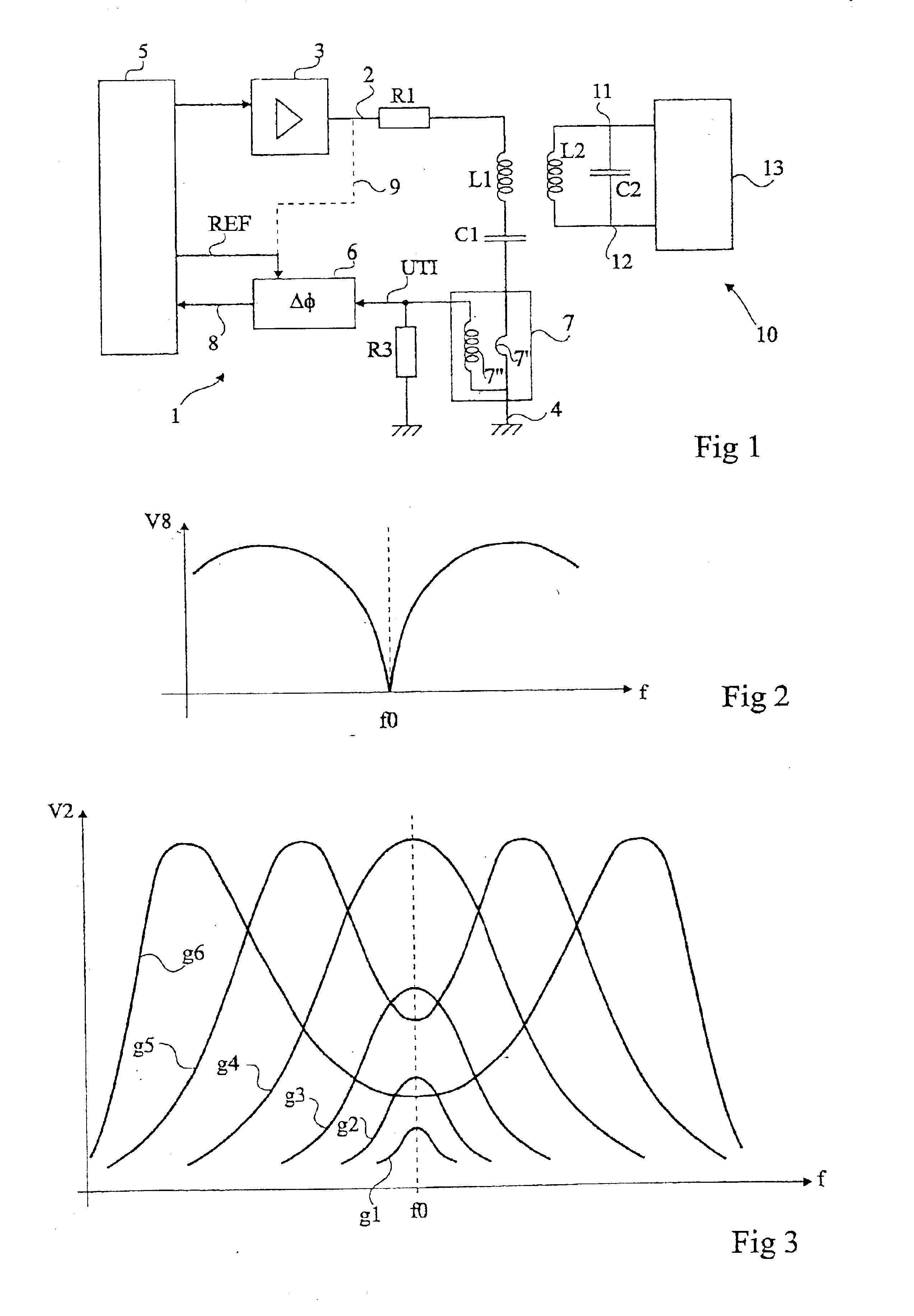
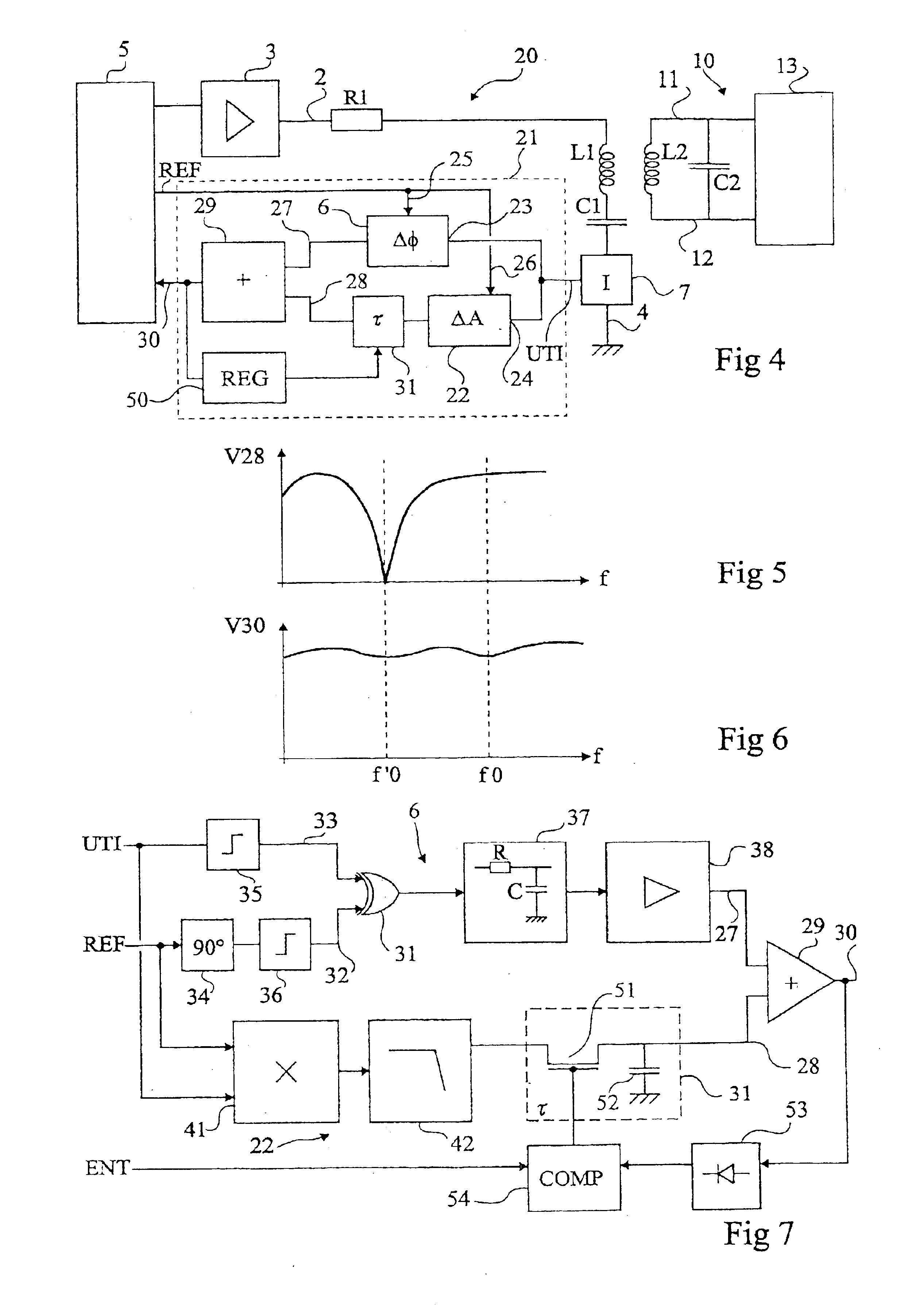
Same elements have been referred to with same references in the different drawings. For clarity, FIGS. 2, 3, 5, and 6 are not to scale. For clarity still, only those elements which are necessary to the understanding of the present invention have been shown in the drawings and will be described hereafter. In particular, the control, processing, and exploitation circuits of the terminal and of the transponder have not been detailed.

A feature of the present invention is to provide, within an electromagnetic transponder read / write terminal, a demodulation circuit which, to extract an image from the transponder's modulation circuit based on a measurement of the signal in the terminal's oscillating circuit, sums up the results of an amplitude demodulation and of a phase demodulation while delaying one of the two results with respect to the other. The delay enables solving problems of synchronization of the two demodulation results. Their sum can then be used, which is considerably simpler...


PUM


Abstract

A method and a circuit for demodulating a signal transmitted by an electromagnetic transponder, including a sensor of a variable which is a function of the load formed by the transponder on an oscillating circuit, a phase demodulator and an amplitude demodulator at least functionally in parallel and receiving a signal coming from said sensor, a summer of the results provided by the demodulators, and a delay element in series with a first one of said demodulators, to compensate for a possible propagation time difference therebetween.

Description

BACKGROUND OF THE INVENTION1. Field of the InventionThe present invention relates to systems using electromagnetic transponders, that is, transceivers (most often, mobile) capable of being interrogated in a contactless and wireless manner by a unit (generally fixed), called a read and / or write terminal. The present invention more generally relates to a read or read / write terminal of transponders which have no independent power supply. Such transponders extract the power supply required by the electronic circuits included therein from the high frequency field radiated by an antenna of the read / write terminal. The present invention applies to such terminals, be they terminals which only read the transponder data (for example, an electronic label), or read / write terminals, which are likely to modify data of the transponder (for example, a contactless smart card).2. Discussion of the Related ArtSystems using electromagnetic transponders are based on the use of oscillating circuits inclu...

Claims


Application Information

Patent Timeline
Patent Type & Authority Patents(United States)
IPC IPC(8): G06K7/00H03D5/00G06K17/00H04B1/59H04B5/02
CPCH03D5/00G06K7/0008
Inventor ENGUENT, JEAN-PIERRE
Owner STMICROELECTRONICS SRL
Why Eureka
Try Eureka