
Packaged chilling systems for building air conditioning and process cooling

Inactive Publication Date: 2005-02-01
TAS ENERGY +1
View PDF13 Cites 63 Cited by
  • Summary
  • Abstract
  • Description
  • Claims
  • Application Information

AI Technical Summary

Benefits of technology

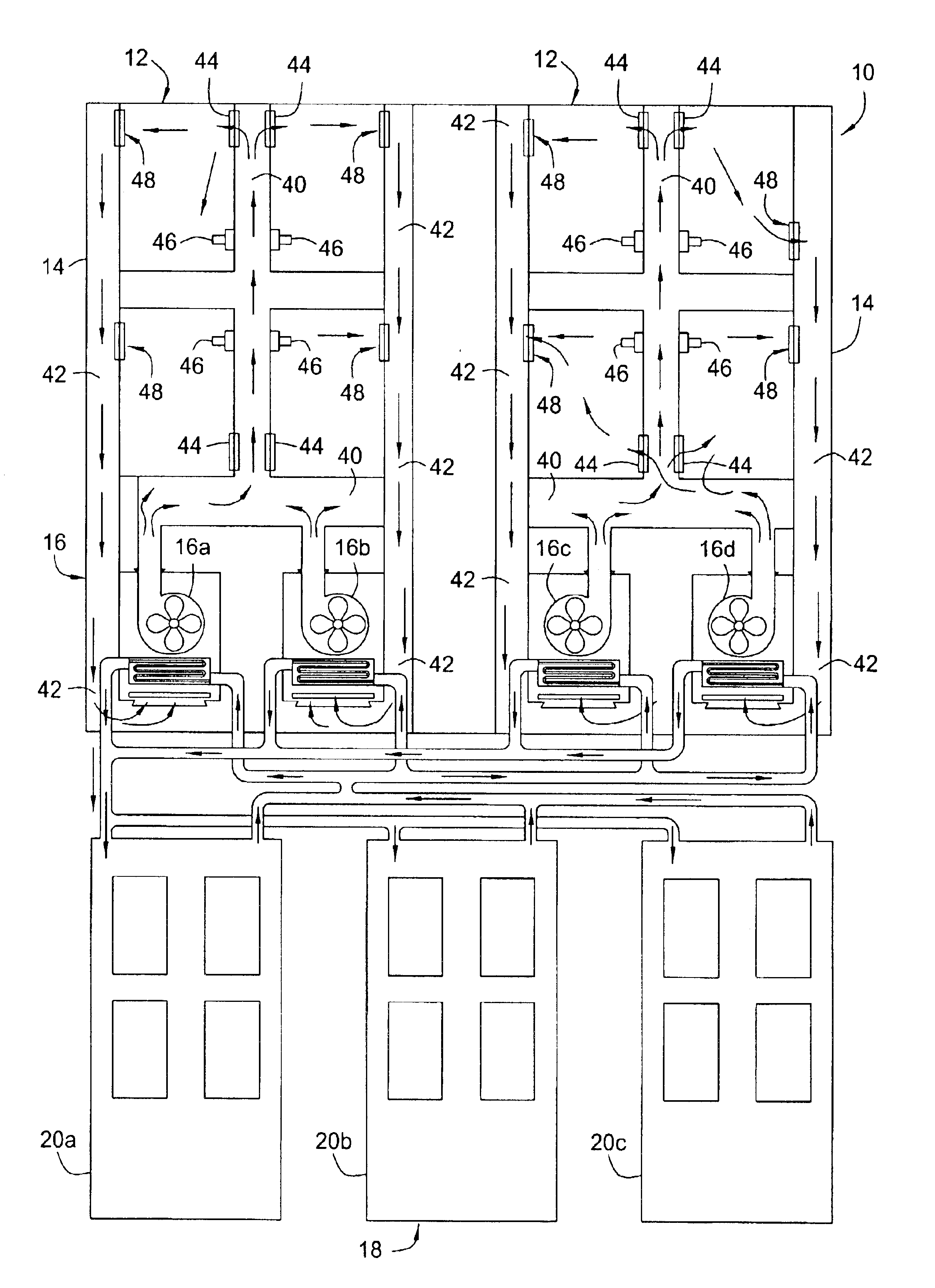
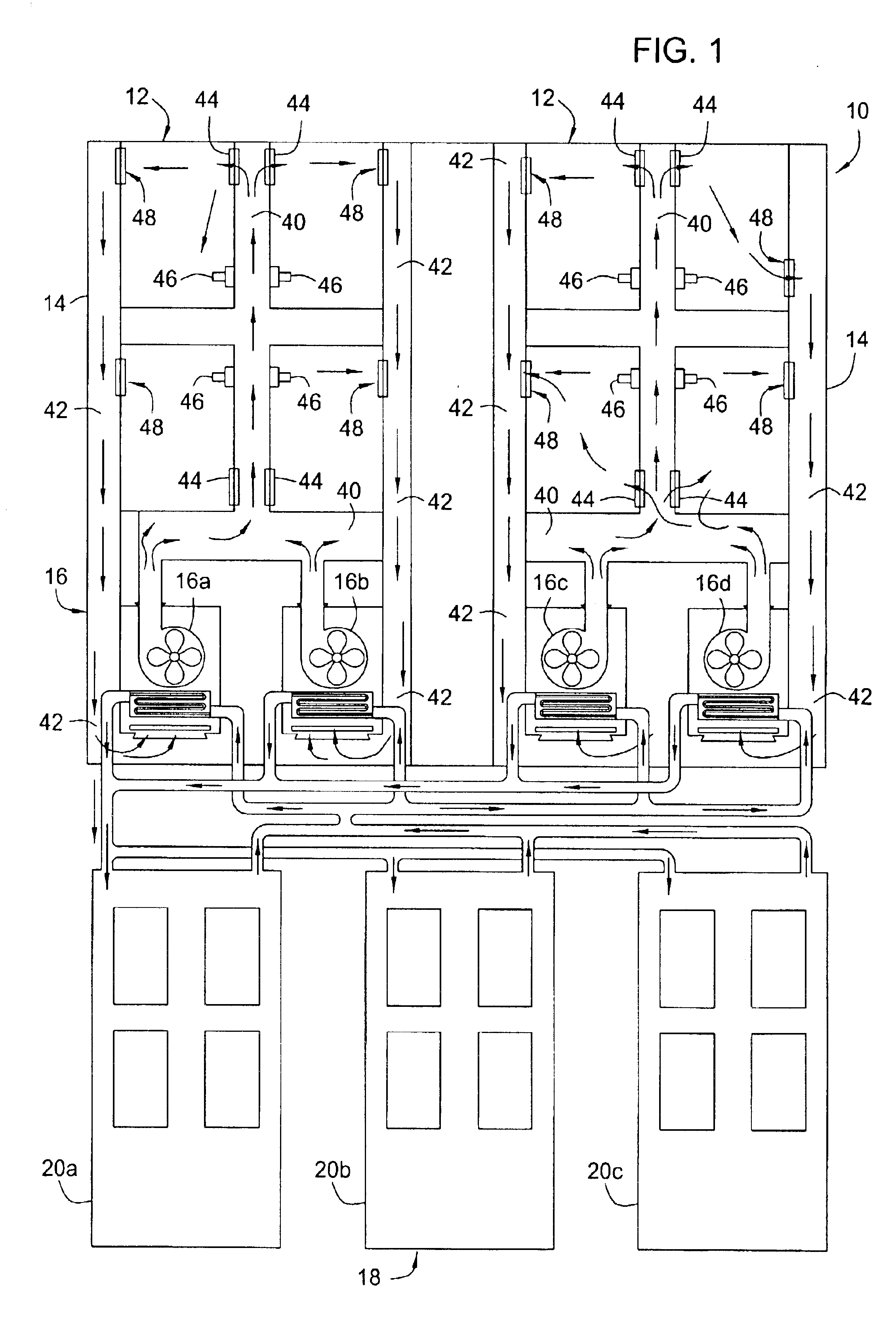
One or more embodiments of air conditioning systems for buildings includes a duct system; an air handling system; and a water chilling system. The duct system is preferably in operable communication with a building that has a plurality of rooms, at least one of the rooms having a sensor for detecting the room air temperature in the room, the duct system including at least one supply duct for directing low temperature air from the air handling system to the building and at least one return duct for directing high temperature air from the building to the air handling system. The air handling system preferably includes a plurality of air handling units, each of which preferably includes an air inlet for receiving high temperature air from the building and a c

Problems solved by technology

Persons skilled in the art have recognized various challenges in designing systems that can be used to control the inside air temperatures in common areas and different rooms of those buildings.
However, installing air conditioning systems and the components of air conditioning systems presents challenges as well.
Installing an air conditioning system is not as simple as it might appear, particularly when the air conditioning system is associated with a building that has numerous rooms, each requiring individual temperature control.
Installing air conditioning systems for large buildings and building systems is often highly complex, requiring the selection and coordination of air conditioning equipment, control systems, electrical switchgear, building materials and supplies, and also organizing the various subcontractors and construction workers, and securing building permits, etc.

Method used


Image

  • Packaged chilling systems for building air conditioning and process cooling
  • Packaged chilling systems for building air conditioning and process cooling
  • Packaged chilling systems for building air conditioning and process cooling

Examples


Embodiment Construction

A. Introduction and Definitions

A detailed description will now be provided. Each of the appended claims defines a separate invention, which for infringement purposes is recognized as including equivalents to the various elements or limitations specified in the claims. Depending on the context, all references below to the “invention” may in some cases refer to certain specific embodiments only. In other cases it will be recognized that references to the “invention” will refer to subject matter recited in one or more, but not necessarily all, of the claims. Each of the inventions will now be described in greater detail below, including specific embodiments, versions and examples, but the inventions are not limited to these embodiments, versions or examples, which are included to enable a person having ordinary skill in the pertinent art to make and use the inventions, when the information in this patent is combined with available information and technology. Various terms as used herei...


PUM


Abstract

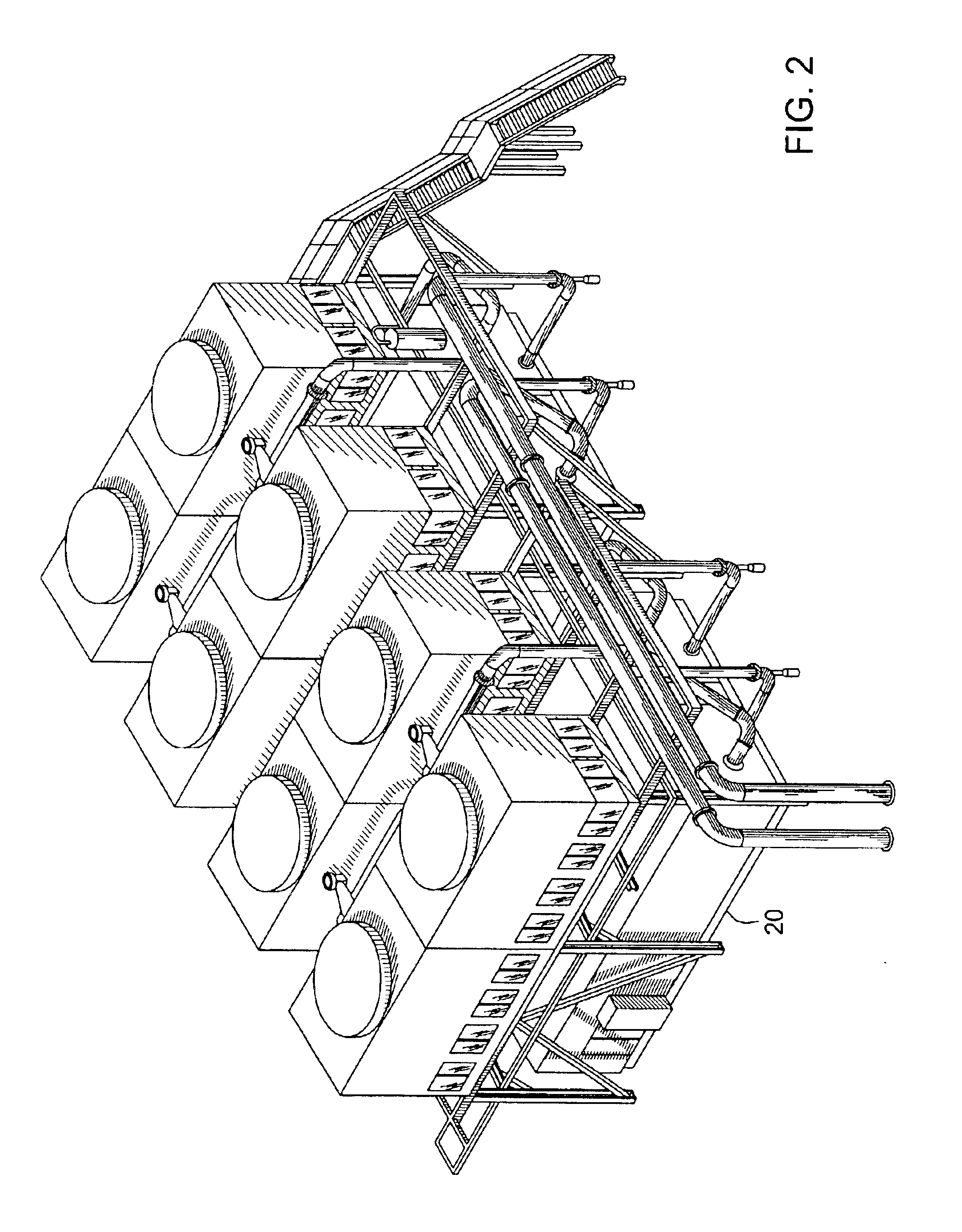
Disclosed is a packaged chilling system for providing chilled water to an air conditioning system for a building that includes: a duct system; an air handling system; and a water chilling system; wherein: the duct system is in operable communication with a building that has a plurality of rooms, at least one of the rooms having a sensor for detecting the room air temperature in the room, the duct system comprising at least one supply duct for directing low temperature air from the air handling system to the building and at least one return duct for directing high temperature air from the building to the air handling system; the air handling system includes a plurality of air handling units, each air handling unit comprising an air inlet for receiving high temperature air from the building, a cooling coil that includes at least one conduit through which chilled water flows, the cooling coil having multiple passes and positioned for heat transfer contact with the high temperature air, and a fan for increasing the velocity of air in the air handling unit; the water chilling system is installed at a location proximate the building, and is operably connected to the air handling system; and the water chilling system includes a moveable support structure comprising a support base on which a plurality of water chilling system components are affixed, the components including at least one water chiller for lowering the temperature of water from a high temperature to a low temperature. This packaged chilling system may also be used to provide chilled water to industrial processes such as chemical plants, automotive plants, textile mills, paper mills, computer cooling, and factory air-conditioning.

Description

BACKGROUND OF THE INVENTION1. Field of InventionsThe inventions described herein generally relate to air conditioning, and particularly to air conditioning systems for buildings and process cooling.2. Description of the Related ArtA continuing need exists for improved air conditioning systems for buildings, particularly large, multi-room and multi-level buildings, e.g., schools, office buildings, hospitals and sports facilities, such as arenas. A variety of air conditioning systems have been proposed and developed, including those described in earlier patents identified on the cover page of this patent. Persons skilled in the art have recognized various challenges in designing systems that can be used to control the inside air temperatures in common areas and different rooms of those buildings. However, installing air conditioning systems and the components of air conditioning systems presents challenges as well. Installing an air conditioning system is not as simple as it might app...

Claims


Application Information

Patent Timeline
IPC IPC(8): F24F5/00F24F3/06F01K23/10F02C7/143F25B27/02
CPCF01K23/10F02C7/143F24F3/06F24F5/0017Y02E60/147F25B27/02F25B2339/047F25B2400/06Y02E60/14Y02P80/10Y02A30/274
Inventor PIERSON, TOM L.
Owner TAS ENERGY
Learn More